


Installing RF antennas properly to the designed position the first time, can prevent added costs associated with a multitude of issues involved in verifying and/or correcting the installation. Over and above the ripple effect of additional engineering, operations, tower crew and back-office costs, there could also be buried costs due to antenna upgrade and installation work.
In addition, there is the opportunity cost of engineering and operations teams re-reviewing data and install packages instead of focusing on more critical performance projects.
The crucial role of the directional antenna as the interface within the wireless environment should not be underestimated. The slightest inaccuracy in the transformation and shaping of the RF signal, due to antenna misalignment, has a critical and sometimes detrimental impact on the performance of the wireless system. Even a 1° to 2° variation can affect network performance as antenna beam widths become tighter and cell site density continues to increase to meet network capacity demands.
While a larger misalignment will result in costly re-climbs and re-visits, bear in mind that this impact should also be studied as a cumulative impact – network wide and not on a single antenna – as audits have proven that as many as 40% of antennas are out of position tolerances. Again, the key issue is not the misalignment of a single sector antenna, but rather how multiple misalignments (even slight ones) will compound into systemic degradation that affects overall network capacity, reduces coverage performance, and negatively impacts return on investment.
Antenna attributes, such as pattern, height, orientation and tilt, are essential elements for the original RF design to be maintained by the network. Deviations in the actual value of these parameters will lower network performance, and can adversely affect the bottom line for both operators and general contractors hired to install and maintain the systems.
Guidelines must be established for adjusting the antenna alignment (azimuth, tilt and roll) during installation of new towers or realignment (audit) of existing antennas.
Adhering to these guidelines is vital for efficient operation of any wireless system, and is even more critical for LTE networks.
Proper antenna alignment is critical to control intra-cell and inter-cell interference, particularly with 4G LTE and upcoming 5G data networks. A key parameter in achieving high data rates in LTE is the ability to maintain high SINR (signal to interference + noise ratio, a quality metric defined by the UE vendor), and high RSRQ (reference signal received quality, a quality metric defined by 3GPP) throughout the cell coverage area. Accomplishing this task is hard enough in close proximity to the tower site, but is considerably more challenging at the cell boundaries where the received signal is at its weakest level and interference is at its highest level.
By having a known antenna position baseline, antenna features like RET (remote electrical tilt) or RAZ (remote azimuth) can be utilised more frequently as changes made from a known starting point now have built-in reliability. Fine-tuning can be more widely and dependably used by engineering and operations staff as a network optimisation method.
LTE and coming technologies also have the promise and potential of self-optimisation (SON). The SON standard (part of the evolving LTE standard led by 3GPP) recommends optimised orientation settings for the antennas and, if allowed by the operator, automatically adjusts the azimuth and tilt of the antennas. For SON to be effective, the actual orientation and location of the antennas needs to match the corresponding data recorded in the SON database, which is based upon the original RF design for each site.
Inconsistencies between the actual and recorded values will render useless the purpose of SON, and may actually degrade, rather than improve, the system optimisation. The same focus on antenna installation accuracy or known antenna position will no doubt help existing RF planning software tools and automatic cell planning (ACP) tools by providing inputs that create more credible outputs.
The effect of azimuth and tilt
Inconsistencies in setting up antenna azimuth and tilt during tower installation will reduce overall network performance. However, the degree of quality degradation depends on the amount of the discrepancy between the designed and installed parameters. Furthermore, inconsistencies in establishing these parameters during installation vary the network coverage and capacity.
Depending on the site and initial coverage area, an adverse cumulative effect will occur if antenna misalignment is greater than 2° azimuth on multiple towers. There will be significant performance and quality issues due to the slight antenna tilt variation of even ±0,25°, as both coverage and quality gaps increase by up to 100% with ±3° of tilt error.
If the dominant serving antenna for a given area is improperly down-tilted, signals at the outer fringes of the target area will be weak and the user will incur greater interference from outside antenna servers. Likewise, if the antenna is incorrectly up-tilted this will lead to the serving antenna interfering with other cells outside of the designed coverage area. Even a +0,5° tilt can bring the main beam above the horizon, causing a host of the issues mentioned.
Many antennas are misaligned, either due to improper installation or environmental conditions shifting the antenna over time, or damage caused from work over antennas on higher installed equipment. Currently, many antennas are aligned using a compass. In these scenarios, a skilled user must adjust for magnetic deviation and be aware of magnetic interference from a host of environmental factors that can skew the results, making it inefficient at best and ineffective at worst. It should be noted that errors are magnified as magnetic deviation increases.
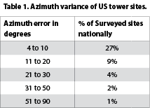
A 2013 audit of US operators showed that 43% of surveyed tower sites had at least one sector antenna with an azimuth error greater than 5° and 16% greater than 10°; and 31% had an m-tilt variance of more than 1°. Table 1 provides a breakout of sites with a given azimuth error.
The real cost of misalignment – repair, adjustment, spectrum, infrastructure and churn
Antenna misalignment has a profound and negative effect on the financial bottom line of both general contractors and operators. Focus often centres on how an ever-so-slight change in antenna direction can dramatically influence the customer experience. Slower upload and download speeds, which can be a direct result of antenna misalignment, result in less data charges for operators, meaning they are not maximising their investment. Poor network performance associated with antenna misalignment can lead to customer churn that can reduce income for operators as well. Additionally, antenna misalignment does not maximise the RF spectrum, which ultimately will limit the number of services and capacity that operators can offer.
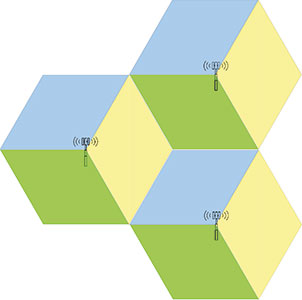
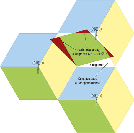
Reducing co-channel interference is critical to maintaining high SINR. In the LTE system all sectors of an antenna site use the same frequency. When sectors of an antenna site are misaligned, unintended RF energy from one sector intrudes on the other sectors of the same antenna site, and also on the sectors of neighbouring sites. Figure 1 shows diagrammatically how even a small alignment error can create intra-site and inter-site interference and coverage gaps.
There are other costs associated with antenna misalignment that are more direct. Billions of dollars have been spent deploying, installing and maintaining 4G LTE networks. Nearly 20% of the operational expenses (OPEX) for these networks are associated with operations and maintenance.
Antenna misalignment falls into that 20%, and can lead to costly site re-visits and re-climbs to correct issues. If general contractors have to deploy teams to adjust antennas on existing base stations, those crews cannot work on new projects that generate income.
Table 2 outlines the costs associated with sending a three-man crew to re-climb and re-verify an existing site. The out-of-pocket costs total approximately $500 but the ‘real’ expense is nearly $5000 – ten times the out-of-pocket cost. This is because there is an opportunity cost that must be considered when the crew can’t move forward to installing or upgrading a new tower site. When considering the fact that 43% of all sites are misaligned at least 4° azimuth, these financial figures become astronomical for general contractors. It should also be noted that unnecessary site re-climbs to correct antenna installs undoubtedly increase the risk of tower climb accidents or fatalities.
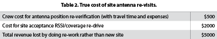
The economic impact of site re-visits is even greater for operators. Estimated out-of-pocket costs associated with having a technician conduct drive tests at an existing site is approximately $2000. Revenue that is lost because the site is delayed from going on-air and from the overall build plan being stalled or pushed out as a result is around $7500 per instance.
The Sunsight AAT-30 enables a legitimate cost saving in the time invested to collect data for the general contractors (GC) and proof that it is done right. Multiple antennas’ data can be reviewed in one simple report as opposed to labelling and saving multiple pictures per antenna.
Standard reporting time requirements can easily add up to be three hours per site at an average cost of $50 to $75 per hour of labour. This additional time that includes capture, data compiling and back office support, is a buried cost for the GC.
The wireless carrier’s RF engineer, or field engineer, who reviews the antenna position information report, can easily review this simple report as opposed to sorting and opening multiple pictures and reports per antenna to verify precise installation, saving a minimum of two hours per site; at $75 to $100 per hour of labour, that’s easily $200 000 per 1000 sites reviewed. Also, consider the missed opportunity cost of the lost time for engineering/operations staff.
Antenna misalignment can have a direct effect on customer satisfaction, driving up complaints and customer churn. Studies of cellular customer behaviour have found that defensive retention is more cost-effective than trying to attract new customers. Studies have also found that heavy users are more likely to churn, because they have higher performance expectations.
In 2010 Nokia-Siemens Networks found that 30% of all churn was primarily caused by customers dissatisfied with voice or data quality or network coverage. It also found that reducing post-paid churn (post-paid is the primary area where churn occurs) by 1% will add 2,76 million Euros to an operator’s bottom line. Any improvement to antenna site alignment that helps network performance can have a very real and positive impact on retention and profitability.
The real cost of misalignment – spectrum inefficiency
Sunsight’s 2015 white paper ‘RF Antenna Misalignment Effects on 4G/LTE Data Throughput’ looked extensively at the effect of antenna azimuth and tilt misalignment on network performance. The paper references a 2013 audit of over 6000 antennas which found that over one third of antennas in real-world systems are installed out of tolerance, and concluded that these errors can have a direct and negative effect on an operator’s bottom line, because spectrum purchased from auctions is not efficiently used – not to mention – upstream infrastructure.
The paper analysed a hypothetical system (1900 MHz PCS, FDD-LTE duplex, with 5 MHz channel bandwidth) covering Santa Clara County, a dense suburban market with a US Census population of 1,78 million people. The paper concluded that conservative losses from typical azimuth misalignment (as found in the 2013 audit) would be about $117 810 for just this market, and extended this estimation to show that a US national operator of 40 000 sites on a 20 MHz FDD system would incur spectrum inefficiency losses of $75,4 million, and that losses would be double for a 40 MHz nationwide system.
The paper also concluded that spectrum inefficiency losses from a minor 0,5° down-tilt misalignment of a single sector in the hypothetical 5 MHz system could be $8369 because of reduced coverage footprint and induced interference.
Proper antenna alignment solution
Costs associated with antenna misalignment can be dramatically lowered by using a proper antenna alignment solution. There are tools that can help broadband LTE networks meet their designed capacity, and ensure the best possible return on the multi-billion dollar investment associated with 4G networks. They help eliminate costly site re-visits and re-climbs, and make sure a tower’s performance is equal to the original RF design. More importantly, they help reduce complaints and churn by providing more reliable data throughput, which leads to increased customer satisfaction.
Not all antenna alignment tools are created equal, and certain performance specifications must be considered. To maximise bandwidth of 4G LTE networks, as well as their investment, many operators are specifying an antenna tilt of ±0,1°. To meet this stringent requirement, as well as others, antenna alignment tools must be highly accurate.
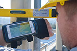
The Sunsight Antenna Alignment Tool (AAT) shown in Figure 2 utilises a unique design with its own advanced accelerometers that allow it to capture downtilt and roll to the less than ±0,5° (3-sigma) mandated by operators. When used to align the azimuth of a sectored cellular antenna, it provides ±0,3° RMS (±0,75° based on three standard deviations also known as ‘R99’) which is well within carrier requirements as strict as ±2,0° for azimuth.
The AAT-30 uses the latest available GPS/GLONASS (GNSS) technology which increases the number of satellites in view and improves positional (horizontal) accuracy. Protected reports can be generated for carriers’ operational departments for construction close-out reports and sent from a device on site to carrier staff if needed.
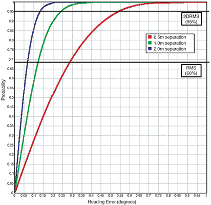
Figure 3 shows the expected probability vs. heading error of the Sunsight AAT solution: 0,5 metre antenna spacing was used that resulted in a ±0,53 R95° (95%) instantaneous heading accuracy. The expected instantaneous performance of the solution should be along the 0,5 m red line. Due to the complexity of the cellular antenna environments (in-band RF, physical obstruction, high-multipath possibilities), as well as the proximity of the GPS antennas to the GPS receiver in the antenna alignment tool, the accuracy specifications were maintained at ±1°, well within the recommended ±2° tolerance of many carriers.
The use of GPS satellites for antenna alignment is vastly superior to a compass and parallels the processes used by most third-party auditors. Using an antenna alignment solution that incorporates the same technology as the auditors helps to eliminate time-consuming disagreements that can lead to added expenses associated with verifying results.
For more information contact Barry Farquharson, ACiRFA Technologies, +27 (0)82 329 7780, barry@acirfa.co.za, www.acirfa.co.za


© Technews Publishing (Pty) Ltd | All Rights Reserved
 printer friendly version