


Apart from the MicroTCA Carrier Hub (MCH), the backplane is a further central element in the MicroTCA system. All data between the individual AMC modules are transferred via the backplane. It is also responsible for the power distribution to the modules. And last but not least it contributes to the mechanical stability of the MicroTCA system. Due to the high transfer volumes and the serial topology, the backplane becomes more and more complex and more of a challenge to the developer.
No parallel bus
The serial data transfer such as used with MicroTCA, uses symmetric cable lines for data transport and is packet oriented. The backplane slots are no longer connected with a parallel bus but via point to point connections. Thus, extremely high transfer rates can be achieved. Current transfer rates range from 1 to 3 Gbps, with 5, 6 and 8 Gbps being achievable in the foreseeable future. The MicroTCA standard stipulates transfer rates of up to 12,5 Gbps, in order to make MicroTCA future secure. Schroff offers MicroTCA backplanes supporting popular protocols such as 1 Gigabit and 10 Gigabit Ethernet, PCI Express, Rapid I/O and serialATA, as well as others.
Different topologies
For the backplanes defined in the PICMG MicroTCA standard, 12 slots are designated for operating units (AdvancedMC modules), one or two for MCHs and up to four for Power modules. Like AdvancedTCA backplanes, MicroTCA backplanes, too, work in a star-shaped network topolgy (as a rule Star or Dual-Star for redundancy) with one or two Hub slots. Full Mesh, such as foreseen for AdvancedTCA, is however not planned for MicroTCA. Through the star-shaped topology, areas with a very high routing density are created on the backplane.
With MicroTCA, the star points, the MCHs, are connected to the backplane with up to four connectors side-by-side, with almost all pins being occupied. On the fairly low height of the connector, approximately 75 mm, these 680 cables have to be led to the pins from the side. Compared to the conditions on an AdvancedTCA backplane, where this number of cables can be distributed over 6 U, the challenge for the MicroTCA backplane become clear, as the same number of cables has to be accommodated in approximately 1,5 U. Without increasing the number of layers, which would make the backplane more expensive, this can only be achieved with extensive effort and experience on the backplane designer's part.
For cost sensitive applications, direct connections between the slots can be realised without star points. In many cases a few slots are sufficient, resulting from the efficiency of the AdvancedMC modules. The number of layers of a backplane can be reduced considerably with directly connected slots and very cost effective solutions can be offered.
Despite the different topologies, the user need not be concerned that a module might be damaged during insertion by an incompatible software protocol. Via so-called Chassis FRU (field replaceable unit) data, stored in an EEPROM on the backplane, the Shelf Manager of the MCH reads the backplane topology and detects the different properties of the AMC modules. Incompatible boards are not permitted to exchange data.
Degree of modification for custom adaptations still within limits
The initial fear that the many possible topologies and module widths could lead to an enormous rise of customer-specific backplanes, has not materialised. Most users have concentrated on Star or Dual-Star topologies. With respect to module widths, the 4 HP width added to the specification subsequently seems to have established itself. Many modules originally arranged in 6 HP, have meanwhile been re-designed as mid-size modules. Compact modules (3 HP) only play a subordinate role now, and the full-size modules (6 HP) are only used for specific boards with very large components. Therefore, a certain number of backplane configurations can be developed, which can then serve as a starting point for customer specific applications. Thus, with minor changes the system topology can be adapted to individual application requirements.
Free ports and different transfer protocols
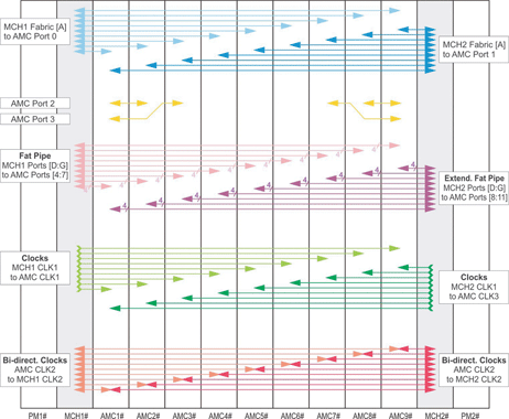
The ports on the AMC module are divided into certain areas for different functions: common options, Fat Pipes and extended options. In the common options area, for instance, the storage interface is located, which serves as a connection to hard drives. To construct a storage server, all HDD slots can be connected via an S-ATA or SAS switch on one or both MCHs in star formation. In all other application scenarios it is sufficient to connect dedicated CPU slots on the backplane via direct links with one or two slots for hard drives.
The main data transfer takes place in the Fat Pipe and the extended Fat Pipe region. There are four ports on each connector, which are connected to MCH 1. The extended Fat Pipe region is used for redundancy. There are also four ports which are led to the MCH 2 and there are still free ports in this region which have not been defined yet. However, suggestions are available from AdvancedMC module manufacturers and the Scope-Alliance how these could be used in future.
In order to use two different transfer protocols in one system it has, for instance, been considered to use only two ports for Gigabit Ethernet and to use the other two for Rapid I/O. Thus, on a board connected via both of these protocols, the switching of both system halves with different software protocols takes place. For the design of the backplane it does not make any difference which protocol is used, but the data exchange on the MCH and the connected AdvancedMC modules are usually protocol dependent. Therefore new thoughts in this direction are to work with two different protocols and half the bandwidth in a MicroTCA system.
New design guidelines are required
Backplanes that can transfer several Gigabits per seconds per port are still subject to the same physical laws as their predecessors, but the conventional design guidelines, that were still in use for parallel VME bus systems and CompactPCI, fail. Loss in the dielectric and the skin effect are beginning to play a large role. Even more critical, however, is the configuration of the vias, the transfer points of signal lines from one layer to the next. The through-contacts, where mostly connectors are pressed in, are creating problems from several perspectives, which could still be ignored with the old 'MHz' buses:
* Resonances are generated in the via through the stub effect, influencing the signal transfer immensely.
* The capacity of the via causes a strong impedance discontinuity, on which the signal energy is reflected thus worsening the signal-hiss relation.
* The capacity of the via has the effect of an underpass and filters the high frequency signal parts that are required for the transfer of the serial protocols.
Back-drilling, a conventional technique to push the resonance frequencies to higher values, the omission of so-called non-functional pads and the creation of the largest possible anti-pads, are only a few measures which can lead to success here. Equally indispensible are calculations before the first design with the aid of 3D field calculation software and simulations.
| Tel: | +27 11 608 3001 |
| Fax: | +27 11 608 1918 |
| Email: | [email protected] |
| www: | www.actum.co.za |
| Articles: | More information and articles about Actum Electronics |


© Technews Publishing (Pty) Ltd | All Rights Reserved
 printer friendly version