


Light emitting diodes (LEDs) are semiconductor devices that emit light when an electrical current passes through them.
The benefits of using LEDs continue to evolve and mature, making them an increasingly viable choice for legacy and new lighting applications.
The benefits of LEDs include a longer operational life, higher energy efficiency (lumens per Watt), and tiny size for small form factors. For example, an LED bulb’s operational life of 50 000 hours far surpasses the typical 1000 to 2000 hours for incandescent lamps and 5000 to 10 000 hours for compact fluorescent lights (CFLs). Consequently, LEDs are well suited for many commercial and industrial applications where energy savings are desired, and where access/safety risks and high labour costs inhibit replacing a lamp.
The brightness of the light emitted by a 10 W LED bulb is roughly equivalent to a 60 W incandescent bulb, making LEDs much lower-cost to operate and maintain. LEDs can be used in legacy form factors like MR16; they are ideal replacements for those sockets and provide longer lasting and more energy efficient lighting.
The wavelength, or colour, of light that an LED emits depends on the materials used in the construction of the LED. With an appropriate driver, LEDs offer more design flexibility for dimming and changing the colour of their emitted light. When combined with an appropriate controller and sensor, they can adjust the amount and colour of emitted light based on changing conditions within the environment.
This capability makes them ideal for applications like indoor lighting, and dimmable street and outdoor lighting that change their brightness as the ambient lighting changes. Dimming LEDs saves energy at roughly a 1:1 ratio, so dimming an LED to 50% will save about 50% of the energy usage.
Designers continue to incorporate LEDs into a growing variety of lighting applications. This article will explore LED implementations in two scenarios. Designers are using LED modules in legacy form factors, such as MR16, to deliver LED lighting benefits where the LED must operate with the existing, legacy power infrastructure. In contrast, Power-over Ethernet (PoE) LED lighting networks operate on newer or parallel power infrastructures. Before discussing these application spaces, a brief review of the LED driver is in order.
The LED driver
LED drivers are low-voltage components that convert input-voltage power, such as 120 V, 220 V or 277 V, to the low voltage that LEDs need. These drivers can also interpret control signals to dim, brighten and change the colour of the emitted light (Figure 1).
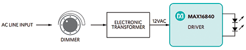
LED drivers are available in either constant-current (e.g. 350 mA, 700 mA or 1050 mA) or constant-voltage (usually 12 V or 24 V) implementations; these two types of drivers are not interchangeable. The fixture manufacturer chooses the driver type and configuration to match the electrical requirements of the LED module used in the fixture. This article focuses on constant-current drivers.
Constant-current drivers support both pulse-width modulation (PWM) and constant-current reduction (CCR) methods for adjusting the output current when dimming the LED. LED applications require a constant current to ensure that the LED light output stays the same even if the input voltage fluctuates.
The LED driver not only drives the range of the high- and low-end light level, but also whether the dimming is continuous or stepped. Designers match the driver and LED based on the intersection of a number of application requirements, including the number of LEDs to drive, the type of power supplied, and the functional characteristics of the LED.
A poorly matched or implemented LED driver can actually shorten the operational life of the bulb and cause undesirable lighting behaviour such as flickering. Flickering occurs when the amplitude and/or frequency of the light emitted from the LED blub periodically modulates or fluctuates (undesirably) so that it is visible to the human eye. LEDs are susceptible to flicker when there is a fast change in their light output caused by rapid changes in the input current.
Flickering is caused by many sources, including line noise, control noise, component tolerance, and poor LED driver circuit design. A good LED driver should account for all of these internal and external factors, to deliver flicker-free dimming by supplying the LED with a constant, non-oscillating electrical current.
Retrofitting
The longer life and better energy efficiency of LEDs make them ideal for replacing other lighting technologies, especially incandescent and halogen lamps. There are two primary challenges when retrofitting an LED into an existing lighting infrastructure. First, the replacement lamp must fit the form factor of the legacy light source and, secondly, it must work correctly and without flickering in the existing electrical infrastructure.
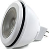
Fitting an LED into an existing form factor, such as the MR16 (Figure 2), limits not only the size of the driver board, but also drives the thermal considerations of the design itself. Because LEDs emit only visible light, they dissipate more heat through thermal conduction than incandescent or halogen lamps. Thermal dissipation is also one of the limiting factors for the amount of light that a lamp can produce.
Today’s LED technology in retrofit lamps can barely achieve a level of brightness that is acceptable for the mainstream market. Pushing the limits of brightness and, consequently, thermal design is essential for designing a commercially successful product.
A corollary issue to thermal dissipation is the lifetime of the driver board. To emit more light, the lamp must work at a fairly high temperature (+80°C to +100°C). At these temperatures, a poorly implemented driver board that is susceptible to high temperatures can limit the operational lifetime of the whole LED lamp.
To work correctly within the existing electrical form factor, retrofit LED lamps must work correctly in infrastructures that include cut-angle (triac/leading or trailing edge) dimmers and magnetic or electronic transformers. Each infrastructure has its own set of technical issues.
Dimmers work well with halogen lamps because the current draw is high enough to ensure that the dimmer stays on. However, an LED retrofit lamp does not allow the triac dimmer to work properly because it provides neither the required start current nor the hold current. As a result, the dimmer does not start properly or turns off while operating, and then the LED lamp flickers.
Electronic transformers have their own design considerations. They require resistive loads, but LED MR16 bulbs are not resistive loads. Therefore, the loading behaviour needs to be modified to keep the electronic transformer from shutting off.
One of the biggest obstacles in LED MR16 bulb design is producing bulbs that are dimmable with no flicker and are compatible with electronic transformers. Electronic transformers, while much smaller than traditional magnetic transformers, present a formidable design problem when supplying the lower current required by LED bulbs. This lower LED current prevents most LED bulbs from operating with electronic transformers.
A dimmer adds to this challenge by reducing the current further.
Maxim’s MAX16840 LED driver uses a proprietary constant-frequency average current-mode control scheme to solve this problem. It is also compatible with most electronic transformers and trailing-edge dimmers.
Power over Ethernet (PoE)
LED lighting is a near-mainstream technology. Additionally, LEDs can be readily paired with sensors, wireless communication modules and embedded processors. This versatility allows LED light fixtures to become smart networked sensor hubs, and lighting systems can experience energy savings using an isolated local embedded processor.
Connecting smart LED lighting/sensor hubs to the local area network (LAN) delivers valuable future-proofing by enabling the installed LED hubs to quickly support and take advantage of emerging capabilities on the IoT (Internet of Things) without an expensive lighting replacement (Figure 3).
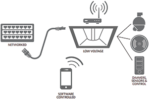
PoE is ideally suited for powering, connecting and controlling smart LED hubs with the LAN. PoE technology is regulated by the IEEE 802.3 standard, which specifies that power and communication data be delivered across a single standard network cable wire (i.e., Cat. 5) directly to the network port of the connected devices.
Using PoE lowers the cost of deploying and installing IP-enabled devices, including LED lighting and sensor hubs. Cabling costs are lower because only a network data cable needs to be run; no separate power cable is needed. Installation costs are lower because a licensed, qualified electrician is not required to run the network data cable.
A PoE network enables better overall network power management, because it provides both discrete control over the power of the connected devices and power backup during power outages with only the network connection. PoE supports 10BASE-T, 100BASETX and 1000BASE-T networks.
The original PoE standard was released in 2003 and updated in 2009. Power is supplied via power sourcing equipment (PSE) located in the switch/hub. The IEEE 802.3 standard also allows a PSE to be used in a midspan to insert power in the network. This approach supports legacy networks and offers more control over which network segments are powered. The connected device receiving the power is commonly referred to as a powered device (PD).
To support legacy installations, the PSE can supply power over two pairs of wires, at a maximum of 15,4 W over a voltage range of 44 V to 57 V d.c. using Cat. 3 or better cabling. The standard also specifies that the PSE can supply 30 W (over two pairs) or 60 W (over four pairs) over a 50 V to 57 V d.c. voltage range using Cat. 5 or better cabling.
For these three power scenarios, the PD is limited to a maximum power draw of 13 W, 25,5 W or 51 W, respectively (to account for worst-case power loss in the cable) – all over a 37 V to 57 V d.c. voltage range. The PD negotiates a power class with the PSE during its initial connection. All PDs include a 25 k resistor across powered pairs, to allow the PSE to detect when a PD connects and disconnects from the network.
PoE does not degrade data communication performance. In fact, it protects the network equipment from overload through negotiation of power consumption between the PoE unit and the connected devices. Power is only delivered to compatible devices and is blocked to incompatible legacy devices. This approach allows users to freely and safely mix legacy and PoE-compatible devices on their network.
In a PoE configuration, each LED fixture can be a standard RJ45 connector plug-and-play device with its own IP address that is individually addressable. Connecting smart LED hubs (with integrated sensors and wireless access points) via PoE provides power for each LED hub to emit light. The PoE connection also enables each LED hub to collect information from its various sensors and communicate the data back to a controller (Figure 4).
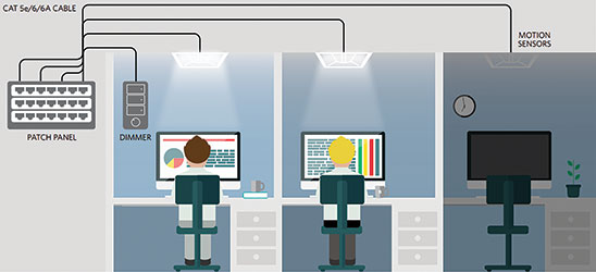
The collected information could include ambient lighting, temperature, humidity and anonymous room occupancy data. For example, occupancy sensors can be used to ensure that lighting is activated only upon someone’s entrance into a space. When the sensors no longer detect the presence of anyone, lighting is automatically turned off. Or, ambient light sensors enable daylight harvesting because the LED lighting is automatically adjusted to maintain lighting when not enough sunlight is present.
Operating over PoE, the LED lighting system becomes an information network so users control the lighting and temperature in their immediate vicinity. The system can access other building services (for example, with a smartphone) like proximity sensors to discover the closest available meeting room. It can also let facility managers better measure, monitor and control other building systems such as heating and ventilation in real time.
With facility managers now doing historical trend analysis on this data, they could identify opportunities for improved energy and operational efficiency.
These opportunities for efficiency include adjusting temperature, lighting and cleaning schedules based on how users actually behave.
A PoE LED network provides additional benefits of future proofing, because the LED lighting (and integrated smart sensor hubs) are already positioned where people will gather. If a facility manager wants to add new sensor or communication modules, such as distributed short-range wireless access points, it will be accomplished at low-margin cost because the power and data are already wired to the most useful locations.
PoE is the future for LED lighting. Maxim LED drivers support a wide voltage range (MAX16832: 6,5 V to 65 V) and output currents (MAX16832: 1 A capable) that are ideal for supporting PoE applications. These drivers support both analog and PWM control for clean dimming without flicker. They support small size requirements by integrating many of the external components, including the MOSFET.
For more information contact CST Electronics, +27 (0)11 608 0070, sales@cstelectronics.co.za, www.cstelectronics.co.za
| Tel: | +27 11 608 0070 |
| Fax: | +27 11 608 0401 |
| Email: | natasha@cstelectronics.co.za |
| www: | www.cstelectronics.co.za |
| Articles: | More information and articles about CST Electronics |


© Technews Publishing (Pty) Ltd | All Rights Reserved
 printer friendly version