


Compared to conventional light sources such as incandescent and halogen lamps, LEDs are widely known for their energy efficiency and robustness, along with an extremely long operating life. In application, the LEDs are typically subjected to various stresses.
Common failure modes include thermal, mechanical or electrical stress, as well as external chemical exposure.
In this article, several main effects of stress and chemical compatibility on LED performance will be illustrated and certain basic guidelines for LED-based applications are provided. Here, the focus will be on compatibility with four key LED packaging components, namely housing materials, lead frame substrates, converter phosphor materials and silicone encapsulations. Moreover, several procedures are described for testing the chemical compatibility of some potentially critical materials in the application of interest.
Construction of LEDs
As illustrated in Figure 1, an LED consists of one or more semiconductor chips (or dies) as a light source; housing material as a means of mechanical stress protection and reflector; lead frame as a medium for electrical connection, thermal dissipation and light reflection; and transparent or translucent (with addition of converter materials) encapsulation for stress buffering, colour conversion or to act as a primary lens.
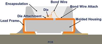
The die can be either glued or soldered onto a lead frame surface. Metal particles (eg, silver or gold) may be added to the die attachment glue for higher electrical conductivity. Depending on the desired colour, the chip types may vary from InGaN to InGaAlP in combination with or without converter usage in an LED device.
The converter pigments, generally one or more phosphor types, are incorporated within the encapsulant or are formulated as a conversion layer attaching to the chip surface. The housing material forms the physical shape of an LED and contributes to a higher light output due to its reflector shape and special filler addition. The housing materials are usually either thermoplastic polymers, silicone or epoxy materials.
A lead frame substrate may be plated with one or more metals to further increase the package robustness or the light output via reflection. In addition, ceramic-based or metal core board type substrates can also be used as a package substrate. Ceramic substrate-based packages (e.g. the Oslon family) are often regarded as having better degradation resistance to humidity, chemical and/or thermal stress.
Regarding encapsulation materials, these may be epoxies, epoxy/silicone hybrids, silicones or glasses. In addition to its mechanical protection function, the encapsulant reduces light coupling losses and directs the LED light towards a specific viewing angle.
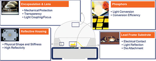
Figure 2 briefly summarises some of the functions of the above-mentioned package materials. As LEDs are usually subjected to high operating temperatures and stress during operation, and are assembled with various materials in the application, certain critical factors affecting LED performance are discussed below. In particular, the compatibility based on each of these four package components is outlined.
Material degradation, corrosion and contamination in LEDs
Despite LEDs’ generally regarded reliability and robustness, they can experience faults and failures resulting, amongst other things, from undesired material degradations or interactions with other system components. LEDs from OSRAM Opto Semiconductors are tested under various robustness test conditions (eg, Steady State Life Test (SSLT) and Temperature and Humidity (T&HB) test according to JEDEC Standards JESD22-A108 and 101).
However, an improper manufacturing and/or packing process or treatment may cause LED module or array damage. For example, incompatible conformal coating and/or excess cleaning solvent (eg, isopropyl alcohol (IPA)) could result in encapsulant swelling/tarnishing or housing material degradation, which may cause LED colour shift or light output decay.
Halogen-containing interconnect materials (eg, fluoride (F-) and/or chloride (Cl-)-containing optics adhesive or solder paste material) could interact with the lead frame and induce lead frame degradation. Thus, electronic grade interconnect materials with high purity and low ionic content are highly recommended. Furthermore, improper packing materials, such as cardboards releasing harmful volatiles and unsealed dry pack bags subjecting LEDs to moisture attack, could cause lead frame discolouration or encapsulant delamination.
This article will focus on material degradation, corrosion and contamination occurring in four key LED packaging components, namely housing materials, lead frame substrates, converter phosphor materials and silicone encapsulations.
LED housing material degradation
The housing material functions as a reflector source to enhance overall LED light output and serves as a protective barrier against various external mechanical stresses. Currently, thermoplastic- and silicone-based pre-moulded packages are widely used in the marketplace. These materials enable a robust LED design under specified storage and operating temperatures.
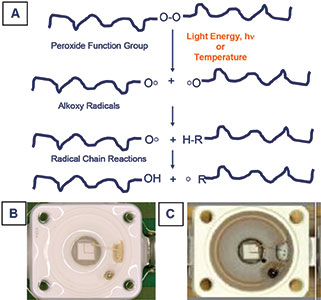
Extreme temperature exposure may cause surface yellowing (browning) of the housing materials and also detachment of the encapsulation material from the housing packages. Oxidation processes at elevated temperature may also lead to material brittleness and discolouration resulting from bond cleavage and structural rearrangement along the polymer backbone structures. During these structural changes, peroxide is formed and free radicals build up which are responsible for material degradation. The degree of degradation is time-dependent and may be accelerated by light, moisture, acid, alkaline and/or coating material incompatibility.
Figure 3 illustrates the concept of thermal oxidation, free radical formation and shows images of thermoplastic-based housing material before and after discolouration occurs. Silicone-based housing material has a relatively high thermal stability. This broader temperature stability range makes silicone, generally, a suitable candidate for LED housings. In general, housing material degradation is induced predominantly by a long-term high operating temperature.
Lead frame corrosion
A metal-plated lead frame substrate in an LED serves as an electrical connector, a heat dissipation medium and a mirror-like reflector. Depending on the application requirements, different metal alloys (NiPdAu, NiAu etc.) can be plated onto the lead frame substrates. As silver has a higher intrinsic reflectivity than other metals, it generally contributes to a better overall light output.
However, silver has a high reactivity which increases its corrosion inclination due to interaction with corrosive gases such as hydrogen sulphide (H2S) and may lead to silver sulphide (Ag2S) formation. Silver sulphide formation can affect silver-containing lead frames (eg, silver or silver-gold plated substrates) – a loose black Ag2S crystal structure can appear on the lead frame surface that may eventually lead to intermittent or open wire bond stitch, and a decrease in light output of as much as 30-40% due to the lower reflectivity of the lead frame material. Copper (even when coated with a thin NiAu layer) or printed circuit boards (PCBs) can also be affected.
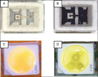
Figure 4 shows examples of Ag2S-affected lead frames; in some situations the effect is even visible through the phosphor-containing encapsulations. To reduce Ag2S-induced failure, great care should be given to the installation of LEDs with silver-containing lead frames. Materials that may release sulphur-containing substances facilitate the silver corrosion risk, eg, sulphur-containing vulcanised elastomers used in O-rings and gaskets should not be integrated in LED applications due to sulphur-containing contaminants, which can penetrate into LEDs.
Besides gases released from the materials in the LED luminaires, for example, in road tunnels, LEDs are sometimes also exposed to a corrosive environment containing SO2 from vehicles, which may result in silver corrosion. Sometimes corrosive environments are unavoidable and thus selection of LEDs suitable for desired field application becomes even more critical. OSRAM Opto Semiconductors offers solutions with certain corrosion-resistance improved LEDs.
To reduce the extent of corrosive gases or chemicals penetrating through the encapsulation barrier, a thin layer of conformal coating can be applied to the LED device surface. Nevertheless, testing of the chemical compatibility of the coating material is highly recommended at the customer side.
Phosphor material degradation
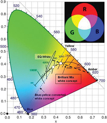
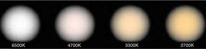
Most LED technologies use the principle of additive colour mixing to generate the desired colour hues. The hue can be either precisely denoted by a Cx-Cy coordinate (Figure 5) or roughly described by a colour temperature (Figure 6). For a more saturated colour, a Cx-Cy description is more representative (the most saturated colours are located at the boundary of the triangle colour diagram, here a visible light spectrum wavelength can be used to well define the colour), whereas for white colour, a colour temperature is more suitable to describe the colour tone (warm or cold white) (Figure 6).
In general, a desired colour can be created by tuning and mixing two or more monochromatic light sources, eg, white light can be typically generated by mixing three primary colours (Red + Green + Blue, known as primary RGB colours) or a single primary colour with its complementary colour (eg, blue + yellow).
The same additive colour mixing method applies to tune the LED colours. Generally, two different methods are used in the industry to generate the desired colours:
• Combination of multiple coloured semiconductor chips (usually the RGB chips) in an LED package.
• Combination of one or more blue semiconductor chips with one or more converter (phosphor) materials.
Although a multiple-chip-containing LED cluster can generate nearly every desired colour, it is typically less efficient than the same colour using the convertor method. It also incurs higher assembly costs because of the need for a more complex driver system.
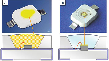
Figure 7 shows two versions of white LED packages, where a blue chip is combined with (yellow) phosphors to generate the desired hue. To tune the colour temperature, more or less yellow phosphor can be adjusted or a mixture of yellow and red phosphors can be utilised. The phosphor materials are either dispersed within the bulk encapsulation material or formulated as a conversion layer attached to the chip surface. For colour-on-demand LED packages, special phosphor mixtures (eg, green, red and/or yellow phosphors) can be tailored to meet almost all colour requests.
As some specific phosphor materials may be sensitive towards acidic as well as alkaline chemicals and humidity, phosphor degradation might occur in such environments and result in non-efficient or inactive colour conversion regions, which could cause LED overall light output change or colour shift. However, phosphors in converted LEDs are relatively inert to an acidic or humid environment. Nonetheless, it is recommended to avoid any potential acidic and alkaline outgassing and humid environments in the proximity of LEDs.
The remainder of this article will be published in our next issue. It will include a thorough analysis of encapsulation discoloration, as well as recommended procedures to test for the various effects described.
For more information contact Petrus Booyens, OSRAM Opto Semiconductors, +27 (0)79 525 1779, [email protected], www.osram-os.com


© Technews Publishing (Pty) Ltd | All Rights Reserved
 printer friendly version