


Ultrasonic range detection can be accomplished with an ultrasonic device added to just an op-amp and a microcontroller with four available I/O pins, including an internal integrated comparator.
To see how this works, take an ultrasonic transmitter that broadcasts a 40 kHz pulse or several oscillations at that frequency. A square wave of one to several wavelengths can be driven from the microcontroller to the ultrasonic device to create the pulse. The pulse is reflected by any object of greater density than air, and part of the emitted pulse returns to the receiver. The round trip travel time can be measured and converted to distance via the speed of sound.
Sound requires a medium to travel through, such as air, water or steel. In general, the denser the medium, the faster sound propagates. The speed of sound in air varies based on temperature, humidity and altitude. At room temperature it can be assumed to be constant at about 343 m/s. This is an ideal speed to use microcontrollers to time the round trip duration of an emitted pulse over a few metres.
The type of reflection surface is not critical; at 40 kHz almost all surfaces reflect the oncoming sound wave. Perpendicular contact with a surface is preferable as the deflected pulses are directed back towards the receiver. As the angle of incidence with the surface increases, the proportion of the pulse reflected back to the receiver decreases.
An ultrasonic transducer operates similarly to a piezo buzzer, but at a higher, inaudible frequency. When an electrical current is passed through the piezoelectric device, it deforms or bends and returns to its original shape when the current is removed. When a 40 kHz square wave is applied to the pins of the device, a 40 kHz sound pulse is radiated. An ultrasonic receiver works in the opposite fashion, producing a voltage, but at a much lower amplitude from incoming ultrasonic sound.
An ultrasonic device can be a transmitter, receiver or both, and be in an open or closed waterproof cover. This demonstration uses separate receive and transmit, open type devices. This type is the easiest to use as a larger drive voltage is required to use waterproof transmitters.
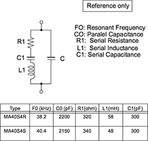
Figure 1 shows the equivalent circuit of an ultrasonic device. It acts as a capacitive load, but because of inductive and capacitive aspects, it is tuned to a 40 kHz resonant frequency. The transmitter is tuned for maximum output while the receiver is tuned for maximum voltage output at an incoming 40 kHz signal. This has an attenuating filtering effect on all other frequencies and is useful in eliminating noise when amplifying the received signal. Typical values for the devices used in the demonstration are listed at the bottom of Figure 1.
Driving an ultrasonic device
Driving the capacitive ultrasonic transmitter with a differential signal gives the greatest transmit strength while maintaining a 0,0 V offset across the device. Driving the pins differentially also eliminates the need for a negative supply to drive the device.
One problem with ultrasonic transducers is they will continue to oscillate or ring after the removal of the drive signal. This ringing is due to the resonant mechanical behaviour of the transducer. The transducer is tuned to ring like a bell at its specified ultrasonic frequency when driven, and it takes a short period of time for the ring to dampen out after the drive is removed.
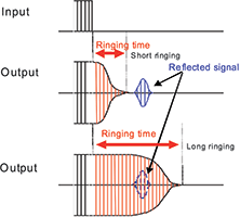
While the transmitter is ringing, the signal will couple through the PCB or travel through the air between the transmitter and receiver, and look like a received signal. Therefore, a delay before the receiver is turned on is needed to ensure the ringing has dampened out, and any signal received is that of a reflected pulse. The amount of time required for the ringing to dampen out determines the minimum detectable distance of the receiver, see Figure 2.
Ultrasonic devices should be driven as close as possible to their specified frequency to increase the output power. The 8 MHz internal oscillator of the Microchip PIC16F690 microcontroller, for example, can easily be divided down to create a 40 kHz drive signal. Two I/O pins of a PIC microcontroller can be used to generate the differential 40 kHz signal that drives the ultrasonic transmitter. This demonstration is using Timer0 interrupt-on-overflow to create the time basis for the output.
An alternative, more automated method of driving an ultrasonic device would be to use the ECCP module offered on many PIC MCUs. The module can be set up to output a PWM of a selected frequency on two pins, P1A and P1B, in half-bridge mode, with one output inverted. The ECCP module uses Timer2 to establish a time base for PWM. Enabling the Timer2 post-scaler lets the user set the number of pulses generated before setting the interrupt flag. This allows an ultrasonic pulse to be sent with a single interrupt.
Once an ultrasonic signal is created and output from the ultrasonic transmitter, the next task is to detect and time a returning reflected pulse. The returning sound wave is significantly attenuated and amplification is necessary before the signal can be detected by a comparator. This amplification can be a single op-amp in a difference amplifier configuration.
Difference amplifier
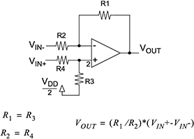
An example circuit for a difference amplifier is shown in Figure 3. This op-amp circuit amplifies the voltage across the ultrasonic receiver connected between the two input pins. The common mode noise at the output is reduced by matching the input bias current through resistors R2 and R4 and resistors R1 and R3.
The ultrasonic receiver acts like a tuned high-Q filter. The difference op-amp amplifies the filtering effect of that receiver. The first op-amp amplifies and filters the incoming signal versus common mode noise. All subsequent op-amp stages will amplify any noise and require additional filters. Selecting the proper op-amp for the first gain stage of the ultrasonic receiver can eliminate the need for more than one op-amp and filters.
This demonstration uses the Microchip MCP6022 op-amp because it has a unity gain bandwidth (UGBW) of 10 MHz. A higher UGBW means the gain of the op-amp is higher at a specified frequency, such as 40 kHz. The demonstration circuit has a gain of 250 to 300 at 40 kHz because the gain is limited by the UGBW and is not described by R1/R2.
A data slicer is a circuit common to many communications applications. A threshold voltage, V_th, is compared with the amplified input to detect the signal. V_th in Figure 4 is set slightly below the average value of the amplified ultrasonic signal, V_US.
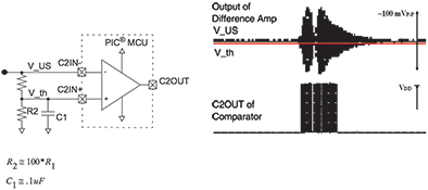
Any time an ultrasonic pulse is amplified, the value at the C2IN- pin will fall below the value of C2IN+, causing the value of the comparator to switch. The value of R2 should be much larger than the value of R1, but not so large it causes the comparator to switch because of noise on the amplified signal. Ideally, R1 is set so the value of the threshold voltage is just above the noise of the received ultrasonic signal. The closer the threshold voltage to the received signal, the greater the detectable distance of the receiver.
The C2OUT pin of the PIC microcontroller can be used to debug this stage of the ultrasonic receiver. A common problem is that the threshold voltage is set incorrectly. If it is too low, the detectable range of the receiver will be limited. If it is too high, the comparator will switch from noise spikes on the line, making it impossible to tell when a signal is present.
The Timer1 gate function provides an enable signal for the clock signal to the 16-bit Timer1 counter. The output of the comparator, C2OUT, can be selected as an internal source to the Timer1 gate. Counting is enabled while the C2OUT signal is low. Once an ultrasonic signal is detected and the C2OUT value changes, counting stops. The value stored in the Timer1 registers is the round trip time in the form of counts of the ultrasonic signal. Depending on the oscillator speed of the device, these counts will have a specific time value.
After detecting the returning ultrasonic pulse, Timer1 stores a count value corresponding to the travel time of the ultrasonic pulse. These counts can be converted to distance by dividing by two and multiplying by the speed of sound. The divide by two is because it is a round trip measurement and can be accomplished by shifting the count value right one bit.
The wavelength of the carrier frequency determines the resolution of the system. A frequency of 40 kHz has a wavelength of about 0,85 cm. Going to a higher carrier frequency increases resolution but narrows directivity and reduces range. Resolution can also be affected by the accuracy of the oscillator used to time the returning pulse, and delays in the signal propagating through a more involved filter. All considered, the resolution for an ultrasonic system operating at 40 kHz can be about 1 cm and does not depend on range, only the returning pulse being detected.
There are two ways of increasing the maximum detectable distance in this application: increased transmission power and increased receiver sensitivity. This demonstration uses I/O pins to drive the transmitter at a maximum of 20 mA and 5 V; MOSFET drivers could be used to boost the drive current and voltage. The gain of the receiver at 40 kHz determines what can be detected by the comparator.
The demonstration uses only one op-amp as a difference amplifier. Because there is only one gain stage, no filtering is needed. A multi-stage receiver would need to do some filtering between the first gain stage and the comparator to reduce noise. Carefully controlling the threshold voltage to the comparator will also ensure that the smallest return pulse is positively detected.
If a separate transmitter and receiver are used, they should both be aligned in the same direction. The transmitted signal and any subsequent ringing will leak through the PCB to the receiver circuitry. Placing more space or a cut-out between the devices on the board will help to reduce this leakage. Ultrasonic transducers are often mounted using rubber or silicon to limit the amount of leaked ultrasonic signal to and from the surrounding material.
Conclusion
Ultrasonic range detection can be accomplished using a PIC16F690, MCP6022 op-amp and Murata MA40S4R/S ultrasonic device. Two port pins of the PIC microcontroller provide enough drive strength to transmit an ultrasonic pulse. Timer0 and Timer1 were used to create a 40 kHz signal and time the returning pulse. The MCP6022 amplified the signal at the receiver, and the PIC16F690 internal analog comparator was used to detect the presence of the returning pulse in the signal.
| Email: | [email protected] |
| www: | |
| Articles: | More information and articles about Tempe Technologies |


© Technews Publishing (Pty) Ltd | All Rights Reserved
 printer friendly version