


Gerber RS-274X is the de facto standard format for printed circuit board (PCB) design software, being utilised for fabricating about 90% of all PCBs designed today worldwide. Yet despite its popularity, Gerber comes with a number of practical limitations, which can lead to a variety of problems throughout the fabrication process.
Fortunately, there are solutions. The open standards Gerber X2 and IPC-2581 were developed to address the problems inherent in RS-274X. What can X2 and IPC-2581 do that RS-274X can’t? Let’s take a closer look at these formats, in order to understand the advantages they provide over the industry standard.
A brief history of Gerber format
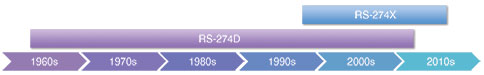
The Gerber file format was developed by the Gerber Systems Corporation (now Ucamco) in the 1960s. A leading provider of early numerical control (NC) photoplotter systems, it developed its first input format to support its vector-based photoplotters. The format was based on a subset of a numerical control standard of the day, known as EIA RS-274-D. In 1980, Gerber Systems published a specification titled 'Gerber Format: a subset of EIA RS-274-D; plot data format reference book'.
This format, commonly known as Gerber RS-274D, or Standard Gerber, was soon widely adopted and became the de facto standard format for vector photoplotters. However, during the 1980s, vector photoplotters began being replaced by raster scan plotters. The newer bitmap based plotters required a completely different data format than that of the earlier, NC based vector photoplotters. Consequently, Gerber Systems extended its original NC format to support a collection of image file formats.
In 1998, Gerber Systems was acquired by Barco and incorporated into its PCB division, Barco ETS, which is known today as Ucamco. At that time, Barco gathered up all of the variants within Gerber’s collection of formats into a single, standard image format known as Extended Gerber or GerberX. The resulting guide outlined the Gerber RS-274X format that is used today.
Gerber RS-274X is a full image description format. This means that an Extended Gerber file contains the complete description of a PCB layer, providing everything needed for an operator to generate a PCB image, and enabling any aperture shape to be defined.
Unlike Standard Gerber, GerberX does not require the support of any additional external aperture files. It specifies planes and pads clearly and simply, without the need for painting or vector-fill. The Gerber RS-274X format quickly superseded Standard Gerber as the de facto standard for PCB image data. It is still used worldwide for fabricating roughly 90% of all PCBs designed today.
Disadvantages of Gerber RS-274X
So, if the GerberX format is so well established and so widely used, then what’s the problem? As it turns out, there are several.
Have you ever received boards with copper layers out of order? Have you ever received boards with drill holes that were mis-registered or even completely missing? Have you ever had to explain to management or a client how a misinterpreted fabrication note caused a schedule delay?
Gerber RS-274X may be extremely accurate and reliable for rendering precise images of copper shapes on signal and plane layers, however the problem is that the standard does not take into account all other aspects of PCB fabrication and assembly.
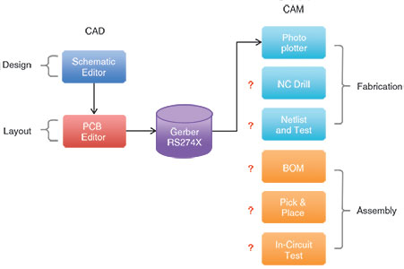
For instance, there’s the transfer of the layer stackup order and materials information, drill data, pick-and-place data, BOM (bill of materials) data, netlist, test point report, and more. All of these other data sets must be generated as a separate process by a separate utility. Simply put, Gerber RS-274X format does not transfer the complete design from the design domain (CAD) to the manufacturing domain (CAM).
Without the transfer of a defined layer order, boards can end up with copper layers out of order during fabrication, or layers missing altogether. Without the transfer of drill data generated by the same process as the Gerber files, holes can end up drilled relative to an incorrect origin, or drilled relative to an incorrect version of the layout. The same goes for all other aspects of the fabrication and assembly data. Missing output data, or any one output generated from the wrong source file version, can render useless boards.
As long as designers maintain a well-defined design methodology and adhere to best practices, they can generally utilise Gerber RS-274X with minimal fabrication issues. However, nobody’s perfect, and even under ideal conditions, problems can still arise. Consequently, the fabricator and assembly houses tend to bear the brunt of the responsibility for sorting through these problems. They’re forced to inspect and verify the data of all incoming jobs, in order to minimise manufacturing issues, spending a great deal of time and resources in the process.
Alternative open standards
In order to eliminate these problems, it’s necessary to adopt a design transfer standard that takes into account all aspects of fabrication and assembly data. Fortunately, two new open standards have recently been released which enable accurate, efficient data exchange between PCB designers and manufacturing fabricators and assemblers. These standards are Gerber X2 (administered by Ucamco) and IPC-2581 (administered by the IPC Consortium). Both Gerber X2 and IPC-2581 are open standards free from proprietary restrictions.
Gerber X2
Gerber X2 comes from an expanded version of GerberX format, which now includes design data, in addition to layout image data. Whereas previously, board layer order and stackup information had to be manually interpreted and verified, now this data is included within the X2 fabrication files. Also included within the X2 fabrication files is a set of drill files detailing the drill size, location, plated/non-plated, and layer span.
New in X2 is an attribute system which further qualifies traditional objects. For example, ‘file function’ specifies the file as top copper layer, top solder mask, etc.; ‘part’ specifies a single PCB or panelised array. ‘Pad function’ specifies a through-hole pad or via, SMT pad, fiducial, and so on. Such attributes add intelligence to the traditional image data for automation purposes.
One of the most convenient benefits of Gerber X2 is that it is both forward and backward compatible with the RS-274X standard. A Gerber X2 reader will interpret Gerber RS-274X files perfectly. This means that a Gerber X2 fabrication process will support legacy fabrication files created in the Gerber RS-247X format.
Similarly, a Gerber RS-247X reader will interpret the RS-274X subset of X2 correctly. So a Gerber RS-247X fabrication process will support a design created in Gerber X2 format just as if it were created in Gerber RS-247X – though of course the NC drill and other applicable outputs would still need to be generated by traditional methods. All Gerber X2 output is directed to one single folder.
IPC-2581
The IPC-2581 standard was initiated, developed and driven by contributors from a wide range of PCB industry segments, such as OEMs, PCB fabricators and contract manufactures, as well as MES, PLM and CAD/CAM vendors. In addition to graphical image data, IPC-2581 goes above and beyond to consolidate all aspects of a design, from layer stackup and materials, to assembly and test details, into a single data format, contained in a single file.
The standard includes detailed layer stack information, which ensures correct layer order and materials information. It easily supports complex board design stackups such as rigid-flex, as well as use of special materials. Also included is drill and mill data supporting blind, buried and filled via types. Back drilling of vias is also supported, as well as V-grooves, slots and cavities. Netlist data are also generated to facilitate bare board testing.
In addition to generating a complete set of fabrication data, IPC-2581 also generates assembly data. The pick-and-place information can specify a location in X/Y and Z locations, as well as component polarity and rotation. This enables support not only for embedded components, but for stacked components as well. In addition, IPC-2581 supports netlist and test point data generation, to facilitate in-circuit, functional or JTAG testing.
IPC-2581 generates purchasing BOM documents, as well as assembly drawings. With ties to PLM/ERP system data, the standard can be used to facilitate links between the design and supply chain. One of the most truly convenient benefits of IPC-2581 is that all of the fabrication and assembly data is contained within a single XML file.
Conclusion
Gerber RS-274X remains the industry standard, used to fabricate the vast majority of PCBs worldwide. However, in today’s design environment, it’s unable to stand on its own. While Gerber RS-274X accurately describes a board’s copper layers, in order to function fully, it must be combined with NC drill, fabrication notes, netlist, and assembly drawing, BOM, pick-and-place data, and more. Combining and managing all of these dissimilar formats typically leads to problems, resulting in production delays, or worse yet, costly and unusable boards.
However, adoption of formats such as Gerber X2 and IPC-2581 allows the combination of all fabrication and assembly data into a single format, helping to minimise or eliminate data translation and human misinterpretation errors as design data is transferred from the design domain to the manufacturing domain.
Gerber X2 and IPC-2581 support within Altium Designer
Altium introduced Gerber X2 capability in the 15.0 release of Altium Designer. This initial implementation was further developed and enhanced in the 15.1 release. The functionality is built in (not a separate extension) and is enabled by default. Gerber X2 output generation can be invoked directly through a menu, or from within a PCB project’s output job file.
Altium also introduced IPC-2581 Rev A capability in the 15.0 release of Altium Designer. This initial implementation was further developed and enhanced to support IPC-2581 Rev B in the 16.0 release. The IPC-2581 functionality must be enabled by installing the appropriate extension.
| Tel: | +27 12 665 0375 |
| Email: | [email protected] |
| www: | www.edatech.co.za |
| Articles: | More information and articles about EDA Technologies |


© Technews Publishing (Pty) Ltd | All Rights Reserved
 printer friendly version