


I received measurement files from a contractor who was working on the installation of premium pre-terminated LC/UPC connector-based assemblies. The contractor’s institutional customer was planning to deploy a 100G migration in the near future and was concerned with future performance.
The data centre was an all SMF (single mode fibre) design, to provide a significant degree of flexibility. The links tested by the contractor were 150 metres long and consisted of five 30-metre segments of SMF fibres that featured 6 LC/UPC connections, as shown in Figure 1.
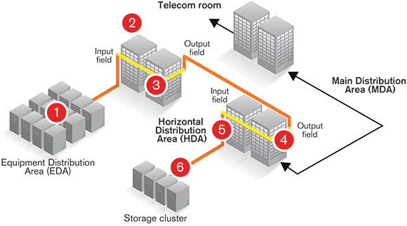
The contractor was using a MAX-945-iCERT unit to perform OLTS (optical loss test set) and ORL (optical return loss) measurement using the FasTest Simplex (singlemode) configuration. Each bidirectional measurement featuring ORL and OLTS took less than 5 seconds per fibre; results included total link loss, length and ORL at two wavelengths.
The contractor configured the unit TIA-568-C.3 for pass/fail notification, to compare the measurements with the inside plant and 100GBASE-LRA standards. He had also configured a custom threshold to validate for a total link loss of maximum 1 dB for both wavelengths and a minimum total Link ORL of 42 dB.
The contractor was experiencing an issue with the fibre 3 measurement. Fibre 5 was perfect and proved to be a good representation of the majority of fibres tested: all results generated a pass notification. With a few hundred fibres remaining to measure, he was still unable to explain the issue affecting fibre 3.
I went to the site with an iOLM-OTDR and proceeded to explain to the contractor that the OLTS is great when everything works fine, but when it comes to telling you where the problem is along the fibre, the effectiveness of the iOLM is simply unparalleled.
The iOLM-OTDR was connected to fibre 3 to identify the issue. We quickly saw that both connector 2 and connector 6 were the cause of high reflection. Connectors 3-4-5 appeared to be OK, while some unusual events, at 219,4 and 377,9 metres respectively, were detected but not identified.
We went over to connector 2 and gently pushed/pulled the connector until a ‘click’ was heard; this connector was inserted into the patch panel, yet it was not pushed far enough in to be in the optimal physical contact condition. The 22 dB Link ORL was an indicator that something close to an open connector was present.
Another attempt was subsequently made with the iOLM: connectors 2 and 6 still were not OK, however it was now clear that connectors 3-4-5 were functioning perfectly. The detailed parameters measured by the iOLM-OTDR, for connectors 2 and 6 respectively, are presented in Table 1.
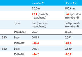
Element pass/fail thresholds were set at 0,75 dB for maximum connector loss and 0,3 dB for maximum splice loss. The maximum connector reflectance was then set at -45 dB; reflectance of -45 dB is an industry recognised target for an intra-DC system running 100G. All of these thresholds were subsequently set for both wavelengths (1310/1550 nm).
The next step of the diagnostic involved the use of the fibre inspection probe, which would then make it possible to put the end face of connectors 2 and 6 under the microscope – see Figures 2 and 3.
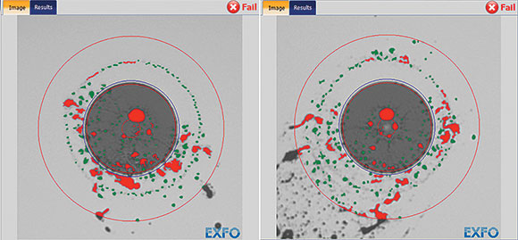
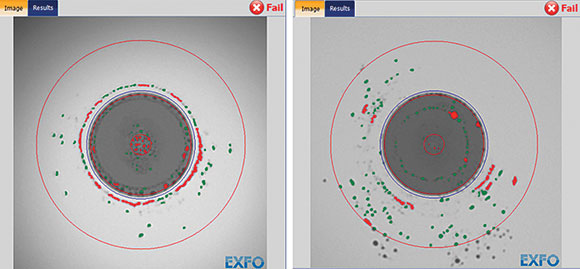
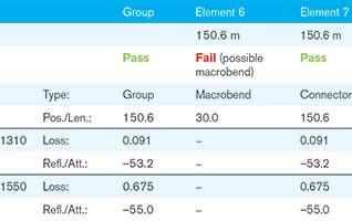
A proper, dry connector cleaner was subsequently used to clean the channel and panel sides of both connectors (2 and 6). Now that the connectors had been cleaned, a final look at the link was definitely in order. Tests showed that all the connectors were clean, however it seemed that a macro bend was hiding behind what appeared to be a dirty connector. The detailed parameters measured by the iOLM-OTDR for connector 6 are presented in Table 2.
Together with the contractor, we proceeded to correctly place the fibre at the patch panel of connector 6 and gave the iOLM-OTDR another try. All the iOLM-OTDR measurements in this test session were performed using the Fast Short Link Optimode, thereby allowing the iOLM-OTDR to perform its measurement in under 10 seconds for two wavelengths for a link less than 2 km. It took a total of 10 seconds to obtain the precise link loss measurement for each connection, including its reflectance, in addition to the total link loss and the total ORL measurement and, finally, a pass/fail diagnostic for the measured link.
The Fast Short Link Optimode will always provide less resolution than the usual Short Link Close Events Optimode (35 seconds’ test time per wavelength), but when the total link is less than 2 km and events are spaced more than 10 metres apart (typical data centre situation), Fast Short Link Optimode is extremely efficient and, no doubt, a second measurement using the Short Link Close Events will provide the additional resolution.
Conclusion
The contractor appreciated the cost saving of a fast test time for the OLTS with ORL (±3 to 5 seconds per measurement). Using the pass fail limits on the OLTS unit, the unit generates pass/fail notification when there is a fail; it is however difficult to locate the exact position of the failed element in the fibre link.
The iOLM-OTDR software shows its effectiveness in identifying the position of the failed elements along the link, especially when the failed elements are identified as being connectors. Fibre inspection proves invaluable as it allows the visualising of the cleanliness of the connector end-face.
The iOLM-OTDR with the Fast Short Link (FSL) allows for mapping the faulty elements, confirming that all elements generate a pass notification in under 10 seconds per measurement, for two wavelengths. This measurement includes all the elements, loss per connection as well as the reflectance per element. Fast Short Link Optimode is ideal to use for single-mode fibre links with a maximum length of 2 km, which represents the clear majority of the existing links in data centre, intra-connect networks.
For more information contact Chris Nel, Lambda Test Equipment, +27 (0)12 349 1341, chris@lambdatest.co.za, www.lambdatest.co.za
| Tel: | +27 12 349 1341 |
| Fax: | +27 12 349 1493 |
| Email: | ockie@lambdatest.co.za, support@lambdatest.co.za |
| www: | www.lambdatest.co.za |
| Articles: | More information and articles about Lambda Test |


© Technews Publishing (Pty) Ltd | All Rights Reserved
 printer friendly version