


One of the challenges synchronisation engineers and technicians often face in the field, is the lack of proper frequency and timing (phase) references required to validate 1PPS clocks’ accuracy and stability at remote sites. This leaves them with one practical choice: the use of GNSS-disciplined oscillators (GPSDO) as reference clocks.
‘Extended’ phase holdover has also been proposed as an alternative reference to help with indoors testing (no GNSS signal). So, it is important to understand how disciplining and the ‘extended holdover’ work, their limitations and how to use them properly, to have a clear and practical idea of what to expect and what not to.
GNSS – GPS in particular – is the best (if not the only practical) option available to get accurate time, timing and frequency almost anywhere in the world. But it is not perfect. Knowing the precautions and GNSS limitations help in defining correct test procedures and setting realistic expectations for field testing.
Basic disciplining introduction
Basically, a GNSS-disciplined clock consists of a high-quality (precision) oscillator that is continuously being corrected using the coordinated universal timing signal (UTC), or standard second, in the form of one-pulse-per-second (1PPS) pulses recovered from the GPS signals. In theory, the rising edge of the 1PPS represents the beginning of a standard second (in practice it is very close).
Frequency and phase are tightly related, but don’t assume that having accurate frequency guarantees accurate phase. In that sense, they are quite different. A disciplining control system will actually make its frequency source slightly inaccurate, on purpose, in order to achieve and maintain accurate phase. There is also noise, jitter, wander and temperature dependence in an otherwise perfect frequency source, which cause random (phase) walk.
Relationship between frequency and phase
A frequency of 1 GHz (1 ns cycle) is used in this simplified example to make mental and visual calculations easier. Figure 1 depicts the relationship between frequency offset and phase drift, which is used in the 1PPS disciplining process to control the position of the output pulse, relative to the standard second. The darker cycles indicate the end of the billionth cycles.
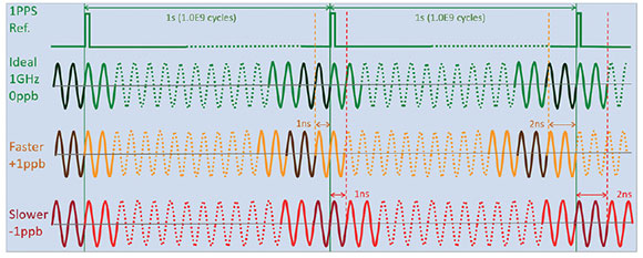
If a 1 000 000 000 counter is used to count one second and the frequency is 1 000 000 001 Hz (+1 ppb), there is one extra cycle (1 ns), which would make the counter roll over earlier, adding about 1 ns phase error for every second that goes by (cumulative). It is similar for 999 999 999 Hz (-1 ppb) as one cycle (1 ns) will be missing from every second, making the counter roll over about 1 ns later, then 2 ns, 3 ns, and so on. That is, positive frequency offset creates positive time drift and negative frequency offset creates negative time drift, at a rate of X ppb = X ns/s.
Frequency disciplining (syntonisation)
To correct any frequency deviation (offset) in the local oscillator, the system could basically count the number of cycles that occur between the rising edges of two consecutive 1PPS pulses (i.e. ‘exactly’ one second). If it is a 10 MHz oscillator and 10 000 010 cycles are counted, then the oscillator is running 1 ppm (1,0E-6) too fast. Then the control system would change (steer) the oscillator’s frequency to slow it down. It counts again and gets 10 000 001 cycles, indicating that the oscillator is now running with 0,1 ppm offset and uses that information to make another correction to perhaps get 9 999 999,9 (-0,01 ppm).
Then finer and finer corrections are made, until the count is as close to 10 000 000,00000 cycles as the system can measure, hence achieving a very high frequency accuracy (e.g. in the order of parts-per-trillion, or 1,0E-12). It continues making those very small corrections to compensate for any changes due to ambient temperature variation and the oscillator’s ageing. Basically, the oscillator is being actively ‘soft’ calibrated in real time and it should now be highly accurate.
One of the caveats here is that the timing signals recovered from GNSS are not ideal. In real life those faint radio signals have to deal with our imperfect world (e.g. ionospheric and atmospheric changes, multi-path, interference, electronics, temperature, etc.). That otherwise ‘perfect’ second varies (wanders) over time. It means that some of the frequency measurements made by the disciplining control system would be a bit off and some slightly wrong correction calculations would be made.
Disciplining systems mitigate this problem by applying some statistical algorithms before issuing the steer correction to the oscillator. Having a high-quality oscillator technology would also help as they are difficult to steer in the short term, creating a dampening effect that helps filter that noise (errors). The end result is a frequency source that benefits from the best of both worlds: the short-term stability of a good oscillator plus the long-term accuracy of GNSS, resulting in a highly accurate and stable frequency source.
Phase/timing disciplining (synchronisation)
This process is very similar to the older frequency-only GPS clocks described earlier, but in this case the priority is to keep the 1PPS phase aligned to the standard second. That is, the control system can intentionally change the frequency of the oscillator to keep the 1PPS phase aligned to the standard second (UTC). As one could imagine, some frequency purists may not like this approach. Imagine starting with a perfectly calibrated 10 MHz oscillator and the first thing the disciplining control system does is to deliberately change its frequency to make the 1PPS pulse drift closer towards its ideal position.
If the oscillator’s 10 MHz disciplined output described earlier is fed to a 10 million counter, it would produce an overflow pulse every time it rolls over from 9 999 999 to zero; that is, every second. Initially the position of the resulting 1PPS output would be arbitrary.
The first task for the phase disciplining control system is to perform a rough alignment, using the GPS 1PPS pulse to reset the counter. This leaves the 1PPS output within 100 ns (one 10 MHz cycle) from the standard second. To fine tune the 1PPS phase alignment to UTC, the control system has to slowly change the oscillator’s frequency.
For example, if the local 1PPS is 30 ns late, the frequency of the oscillator is slightly increased to count faster and start reducing the phase error (absolute time error). On the other hand, if the local 1PPS happens before UTC (e.g. 25 ns earlier), the oscillator is slowed down to delay the counter. It could be said that the amount of new frequency offset corrections are proportional to the remaining time error (plus some amount of vendor-specific statistical magic). It means that the local phase should slowly converge towards UTC and the amount of frequency offset (inaccuracy) in the output also reduces. Once this convergence happens, the GNSS clock should be outputting fairly accurate and stable 1PPS timing and 10 MHz frequency references.
In the absence of any other references or instruments to confirm accuracy and stability, field users should monitor the ±T value (input vs. output) to identify when the disciplining has converged (horizontal trend at 0 ns). At that point, the test set should have reached the best accuracy it could possibly get under the existing conditions.
Why don’t we just use the 1PPS directly from the GNSS/GPS receiver? Firstly because it is quite noisy and needs to be stabilised, and secondly because it could go away at any time, so a good local oscillator is required to help bridge any outages (holdover).
Disciplining for synchronisation testing in the field
An instrument’s internal precision clock can be disciplined by either connecting it to a highly accurate and stable 1PPS, from a traceable Cs or Rb timing reference (e.g. PRTC), or using the 1PPS from a built-in GNSS receiver.
The first option is much faster, more accurate and should provide longer and more predictable holdover. But if we had access to PRTCs in the field, we would use them for testing, directly. There would be no need for extended holdover. Nonetheless, direct disciplining can come in handy in central offices, labs, data centres, etc., where there is a need to quickly transport accurate timing within the premises, to avoid long cables (cables add phase error). So, we are left with the second option and the rest of this article focuses on GNSS disciplining for field testing.
Using GNSS disciplined clocks for testing
High-quality GNSS clocks are excellent timing and frequency references for frequency accuracy (offset) and stability measurements (wander); 1PPS phase accuracy (absolute time error) and stability measurements (wander); and one-way delay (latency) and asymmetry measurements.
Keep in mind that not all GPS receivers are necessarily good GPS clocks. There are different qualities of GPS clocks using Cs, Rb, DOCXO, OCXO or even TCXO oscillators. The oscillator’s quality plays a key role in the GNSS clock performance required for test and measurements. Atomic clock technology is preferred for test and measurement.
When performing frequency-related tests, such as wander (TIE, MTIE, TDEV), cable lengths may have not been an issue. With time error the situation is completely different. Every metre of cable introduces about 5 ns delay (error) which can add up very quickly.
The antenna cable length must be properly documented and programmed into any stationary GNSS clock for 1PPS delay compensation. Test cables (from DUT and 1PPS reference) must be of the same length to cancel out their respective delays.
The continuation of this article, which covers the ins and outs of holdover, will be published in the next issue of Dataweek.
For more information contact Chris Nel, Lambda Test Equipment, +27 (0)12 349 1341, chris@lambdatest.co.za, www.lambdatest.co.za
| Tel: | +27 12 349 1341 |
| Fax: | +27 12 349 1493 |
| Email: | ockie@lambdatest.co.za, support@lambdatest.co.za |
| www: | www.lambdatest.co.za |
| Articles: | More information and articles about Lambda Test |


© Technews Publishing (Pty) Ltd | All Rights Reserved
 printer friendly version