


Charging and discharging batteries is a chemical reaction, but lithium-ion (Li-ion) is claimed to be the exception. Battery scientists talk about energies flowing in and out of the battery as part of ion movement between anode and cathode. This claim carries merits but if the scientists were totally right, then the battery would live forever. They blame capacity fade on ions getting trapped, but as with all battery systems, internal corrosion and other degenerative effects also known as parasitic reactions on the electrolyte and electrodes still play a role.
The Li-ion charger is a voltage-limiting device that has similarities to the lead acid system. The differences with Li-ion lie in a higher voltage per cell, tighter voltage tolerances and the absence of trickle or float charge at full charge. While lead acid offers some flexibility in terms of voltage cut off, manufacturers of Li-ion cells are very strict on the correct setting because Li-ion cannot accept overcharge. The so-called miracle charger that promises to prolong battery life and gain extra capacity with pulses and other gimmicks does not exist. Li-ion is a ‘clean’ system and only takes what it can absorb.
Charging cobalt-blended Li-ion
Li-ion with the traditional cathode materials of cobalt, nickel, manganese and aluminium typically charge to 4,20 V/cell. The tolerance is ±50 mV/cell. Some nickel-based varieties charge to 4,10 V/cell; high capacity Li-ion may go to 4,30 V/cell and higher. Boosting the voltage increases capacity, but going beyond specification stresses the battery and compromises safety. Protection circuits built into the pack do not allow exceeding the set voltage.
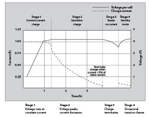
Figure 1 shows the voltage and current signature as lithium-ion passes through the stages for constant current and topping charge. Full charge is reached when the current decreases to between 3% and 5% of the Ah rating.
The advised charge rate of an energy cell is between 0,5°C and 1°C; the complete charge time is about 2–3 hours. Manufacturers of these cells recommend charging at 0,8°C or less to prolong battery life; however, most power cells can take a higher charge C-rate with little stress. Charge efficiency is about 99% and the cell remains cool during charge.
Some Li-ion packs may experience a temperature rise of about 5ºC when reaching full charge. This could be due to the protection circuit and/or elevated internal resistance. Discontinue using the battery or charger if the temperature rises more than 10ºC under moderate charging speeds.
Full charge occurs when the battery reaches the voltage threshold and the current drops to 3% of the rated current. A battery is also considered fully charged if the current levels off and cannot go down further. Elevated self-discharge might be the cause of this condition.
Increasing the charge current does not hasten the full-charge state by much. Although the battery reaches the voltage peak quicker, the saturation charge will take longer accordingly. With higher current, stage 1 is shorter but the saturation during Stage 2 will take longer. A high current charge will, however, quickly fill the battery to about 70%.
Li-ion does not need to be fully charged as is the case with lead acid, nor is it desirable to do so. In fact, it is better not to fully charge because a high voltage stresses the battery. Choosing a lower voltage threshold or eliminating the saturation charge altogether, prolongs battery life but this reduces the runtime. Chargers for consumer products go for maximum capacity and cannot be adjusted; extended service life is perceived to be less important.
Some lower-cost consumer chargers may use the simplified ‘charge-and-run’ method that charges a lithium-ion battery in one hour or less without going to the stage 2 saturation charge. ‘Ready’ appears when the battery reaches the voltage threshold at stage 1. State-of-charge (SoC) at this point is about 85%, a level that may be sufficient for many users.
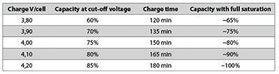
Certain industrial chargers set the charge voltage threshold lower on purpose to prolong battery life. Table 1 illustrates the estimated capacities when charged to different voltage thresholds with and without saturation charge.
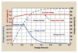
When the battery is first put on charge, the voltage shoots up quickly. This behaviour can be compared to lifting a weight with a rubber band, causing a lag. The capacity will eventually catch up when the battery is almost fully charged (Figure 2). This charge characteristic is typical of all batteries. The higher the charge current is, the larger the rubber-band effect will be. Cold temperatures or charging a cell with high internal resistance amplifies the effect.
Estimating SoC by reading the voltage of a charging battery is impractical; measuring the open circuit voltage (OCV) after the battery has rested for a few hours is a better indicator. As with all batteries, temperature affects the OCV, so does the active material of Li-ion. SoC of smartphones, laptops and other devices is estimated by coulomb counting.
Li-ion cannot absorb overcharge. When fully charged, the charge current must be cut off. A continuous trickle charge would cause plating of metallic lithium and compromise safety. To minimise stress, keep the lithium-ion battery at the peak cut-off as short as possible.
Once the charge is terminated, the battery voltage begins to drop. This eases the voltage stress. Over time, the open circuit voltage will settle to between 3,70 V and 3,90 V/cell. Note that a Li-ion battery that has received a fully saturated charge will keep the voltage elevated for longer than one that has not received a saturation charge.
When lithium-ion batteries must be left in the charger for operational readiness, some chargers apply a brief topping charge to compensate for the small self-discharge the battery and its protective circuit consume. The charger may kick in when the open circuit voltage drops to 4,05 V/cell and turn off again at 4,20 V/cell. Chargers made for operational readiness, or standby mode, often let the battery voltage drop to 4,00 V/cell and recharge to only 4,05 V/cell instead of the full 4,20 V/cell. This reduces voltage-related stress and prolongs battery life.
Some portable devices sit in a charge cradle in the ON position. The current drawn through the device is called the parasitic load and can distort the charge cycle. Battery manufacturers advise against parasitic loads while charging because they induce mini-cycles. This cannot always be avoided and a laptop connected to the AC main is such a case. The battery might be charged to 4,20 V/cell and then discharged by the device. The stress level on the battery is high because the cycles occur at the high-voltage threshold, often also at elevated temperature.
A portable device should be turned off during charge. This allows the battery to reach the set voltage threshold and current saturation point unhindered. A parasitic load confuses the charger by depressing the battery voltage and preventing the current in the saturation stage to drop low enough by drawing a leakage current. A battery may be fully charged, but the prevailing conditions will prompt a continued charge, causing stress.
Charging non-cobalt-blended Li-ion
While the traditional lithium-ion has a nominal cell voltage of 3,60 V, Li-phosphate (LiFePO) makes an exception with a nominal cell voltage of 3,20 V and charging to 3,65 V. Relatively new is the Li-titanate (LTO) with a nominal cell voltage of 2,40 V and charging to 2,85 V.
Chargers for these non cobalt-blended Li-ions are not compatible with regular 3,60 V Li-ion. Provision must be made to identify the systems and provide the correct voltage charging. A 3,60 V lithium battery in a charger designed for Li-phosphate would not receive sufficient charge; a Li-phosphate in a regular charger would cause overcharge.
Overcharging lithium-ion
Lithium-ion operates safely within the designated operating voltages; however, the battery becomes unstable if inadvertently charged to a higher than specified voltage. Prolonged charging above 4,30 V on a Li-ion designed for 4,20 V/cell will plate metallic lithium on the anode.
The cathode material becomes an oxidising agent, loses stability and produces carbon dioxide (CO2). The cell pressure rises and if the charge is allowed to continue, the current interrupt device (CID) responsible for cell safety disconnects at 1000 – 1380 kPa (145–200 psi). Should the pressure rise further, the safety membrane on some Li-ion bursts open at about 3450 kPa (500 psi) and the cell might eventually vent with flame.
Venting with flame is connected with elevated temperature. A fully charged battery has a lower thermal runaway temperature and will vent sooner than one that is partially charged. All lithium-based batteries are safer at a lower charge, and this is why authorities will mandate air shipment of Li-ion at 30% state-of-charge rather than at full charge.
The threshold for Li-cobalt at full charge is 130ºC–150ºC; nickel-manganese-cobalt (NMC) is 170ºC–180ºC and Li-manganese is about 250ºC. Li-phosphate enjoys similar and better temperature stabilities than manganese.
Lithium-ion is not the only battery that poses a safety hazard if overcharged. Lead- and nickel-based batteries are also known to melt down and cause fire if improperly handled. Properly designed charging equipment is paramount for all battery systems and temperature sensing is a reliable watchman.
Summary
Charging lithium-ion batteries is simpler than nickel-based systems. The charge circuit is straightforward; voltage and current limitations are easier to accommodate than analysing complex voltage signatures, which change as the battery ages. The charge process can be intermittent, and Li-ion does not need saturation as is the case with lead acid. This offers a major advantage for renewable energy storage such as a solar panel and wind turbine, which cannot always fully charge the battery. The absence of trickle charge further simplifies the charger. Equalising charge, as is required with lead acid, is not necessary with Li-ion.
Consumer and most industrial Li-ion chargers charge the battery fully. They do not offer adjustable end-of-charge voltages that would prolong the service life of Li-ion by lowering the end charge voltage and accepting a shorter runtime. Device manufacturers fear that such an option would complicate the charger. Exceptions are electric vehicles and satellites that avoid full charge to achieve long service life.
Simple guidelines for charging lithium-based batteries
• Turn off the device or disconnect the load on charge to allow the current to drop unhindered during saturation. A parasitic load confuses the charger.
• Charge at a moderate temperature. Do not charge at freezing temperatures.
• Lithium-ion does not need to be fully charged; a partial charge is better.
• Not all chargers apply a full topping charge and the battery may not be fully charged when the ‘ready’ signal appears; a 100% charge on a fuel gauge may be a lie.
• Discontinue using charger and/or battery if the battery gets excessively warm.
• Apply some charge to an empty battery before storing (40%–50% SoC is ideal).
For more information contact Michael Rogers, Uniross Batteries, +27 (0)11 466 1156, [email protected], www.uniross.co.za
| Tel: | +27 11 466 1156 |
| Fax: | +27 11 466 9109 |
| Email: | [email protected] |
| www: | www.uniross.co.za |
| Articles: | More information and articles about Uniross Batteries |


© Technews Publishing (Pty) Ltd | All Rights Reserved
 printer friendly version