


5G mobile communications networks will be based on virtualised architecture – specifically, a network functions virtualisation (NFV) standard – which is an evolution of the centralised radio access network (C-RAN).
However, 5G is more than just an architecture. It also brings optimal performance requirements, such as huge throughput performance for advanced video services, with less than 1 ms latency, for services such as real-time Internet of Things (IoT).
LTE Advanced Pro bridging the gap
5G is still far off, with a target for massive deployments scheduled for 2020, and mobile operators thus need to stretch existing LTE-A networks to address some of the 5G requirements with accurate performance figures. The pressure is therefore on mobile operators to adopt a C-RAN architecture.
LTE Advanced Pro (3GPP Release 13), and 5G requirements later on, will have an impact on the RAN and fronthaul parts of the network, in particular. A key part of a C-RAN/Cloud-RAN architecture is the optical distribution network. The challenge is to reach each cell site and small cells with a high-performance optical network. In fact, the 5G-PPP group, which is the European committee for mobile telecommunications standardisation, identified the availability of an ad hoc optical network as the major roadblock to successful 5G deployment.
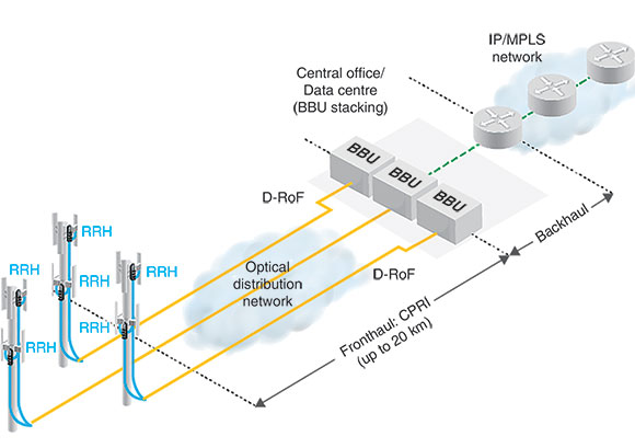
Considering how critical it is for the distribution of the fronthaul signal to be transported over the optical network from the baseband unit (BBU) to each remote radio head (RRH), it is very important to pay close attention to several parameters during the deployment and operation of a C-RAN/Cloud-RAN network.
Operators must accelerate their path to 5G
Mobile operators are facing several challenges like the shortage of spectrum to grow the data throughput and serve more subscribers with video services and other bandwidth hungry applications on smart devices. In addition, they are looking for new sources of revenue, such as from the IoT.
5G will address these expectations through apparently contradictory requirements: 10 to 100 times the throughput, 10 times lower latency, and 10 to 100 times more connected devices. Tier 1 operators are accelerating trials of 5G radio technologies and evaluating new bands, like 5 GHz or 28 GHz radio bands with 200 MHz basebands, which are 10 times wider than what is currently used in LTE.
5G is a game changer because it enables new use cases. 5G-PPP identified three classes (known as verticals), each having its own requirements for radio access:
1. Extreme mobile broadband (eMBB), for example, offers 4K video. Increasing the throughput at the backhaul level will increase the bit rate of the fronthaul as well. (1 Gbps throughput would require a common public radio interface (CPRI) rate above 15 Gbps).
2. Massive machine communication (MMC), for example, offers connectivity to billions of IoT devices. IoT embraces numerous very different applications/business segments. Some of them require deep analytics with regards to the data being received from the sensors and other devices. More processing will have to be done in the RAN at the BBU level, based on mobile edge computing (MEC) technology.
3. Critical machine communication (CMC) will play a role for several industries. For example, for production (remote robot control) to delivery (piloting drones). These require ultra-low latency (1 ms) and high reliability. Fronthaul performance will subsequently be key to meeting these high requirements.
Network slicing, based on virtualisation and C-RAN
The standardisation of 5G is based on the concept of network slicing. Each slice supports a profile of end users with specific performance parameters (latency, accuracy, data rate, coverage, etc.). This approach requires the virtualisation of the mobile network (NFV), where all the slices share the same infrastructure, including the radio network.
The slices for each of the 5G verticals can be very diverse in performance, so real-time coordination of the radio resources is necessary in order to serve all the slices according to their performance requirements. Such coordination can only be achieved by using a centralised RAN.
Pressure on RAN centralisation
Before any mass deployment of 5G, mobile operators will keep improving the capabilities of LTE with new standards, like 3GPP Release 13 and the branded version of 4G: LTE Advanced Pro.
To reach the 1 Gbps throughput target, new techniques, like coordinated multipoint (CoMP), will be used. CoMP requires a shorter path between RRH locations, through the X2 interface. The X2 delay must be much lower than 5 ms to benefit from the CoMP technology. This is difficult to achieve without a centralised RAN architecture (see Figure 1).
There are several other benefits of adopting C-RAN for mobile operators. These include lower capex and opex, since antennas site are simplified (no BBU cabinet), energy consumption is reduced by approximately 50%, and efficiency is improved for the field service team. It also provides for more flexible operation, as the pool of BBUs are in a secured place, which means that more field service jobs (maintenance) can be carried through from the central office, thus reducing truck roll cost).
C-RAN technical requirements
The C RAN architecture involves some specific requirements, like the maximum distance between the BBU and the RRHs.
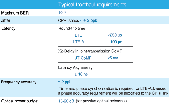
The round trip time (RTT) of the HARQ (packet handshaking protocol) must be less than 3 ms. Consequently, the optical distance between the RRH and the BBU is limited to 15 - 25 km (it may vary between RAN vendors). Most of this RTT is induced by the BBU Layer 1.
Power budget is also an important para-meter to consider, specifically in the case of a passive optical network (typical budget is 15 - 20 dB). The power budget is affected by wavelength division multiplexing (WDM) mux/demux, connectors, splices, bended fibres, etc.
Some difference in latency between the downlink and the uplink fronthaul connections may be required or apparent. This is known as latency asymmetry (see Table 1).
In the future, another challenge imposed on fronthaul will be the required increase in the CPRI bit rate. In general, the basic rule is that the CPRI rate is 16 times that of the data rate on the backhaul (for example, 2,4 Gbps CPRI means that 150 Mbps is required for LTE service). Thus, we can anticipate that the bit rates will exceed 10 Gbps in the future to support the 1 Gbps throughput, which is what LTE Advanced Pro is promising. Some compression will be possible certainly, but this will have its limitations.
This will be the breaking point where designing, deploying and trouble- shooting a RAN will require specific optical networking skills. Optical engineers understand that, beyond a 10 km distance and above 10 Gbps throughput, optical fibres may be subject to dispersion (CD and PMD).
Cloud-RAN and BBU virtualisation
The natural evolution of C-RAN will consist of the virtualisation of the BBU functions. While the virtualisation of the mobile core network is already in progress (based on the impressive efforts of ETSI NFV and all the vendor initiatives) with virtualised IP multimedia subsystem (vIMS) and virtualised evolved packed core (vEPC) networks, the next phase of mobile network virtualisation is the RAN. Moreover, there are significant financial benefits for this transformation given that the RAN is the costlier network segment. As discussed earlier, 5G and its network slicing concept require precisely this kind of virtualised network (see Figure 2).
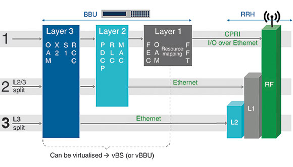
A BBU fulfils several functions, some with strict real-time constraints, others that include software-based protocols. Vendors are splitting these functions into three layers.
Layer 1 includes real-time digital RF processing, alarms and error handling (OAM), and error correction (FEC). For the time being, this layer is difficult to virtualise. Layers 2 and 3 consist of MAC/RLC and interface protocol software. These layers could run as virtual network functions (VNFs) in the NFV cloud.
With the splitting of Layer 1 and its relocation in the RRH, there is the possibility of using the more flexible transport protocol Ethernet instead of CPRI in what is referred to as packet-based fronthaul. If Layers 2 and 3 are running in an NFV cloud, the connection from the access/edge data centre and the cell site becomes a new type of interface, and they require a combination of backhaul and fronthaul.
New definition of fronthaul
The main reason the bit rate on the CPRI interface is so high is the digitisation of the baseband RF signal before its transmission through the fronthaul. The relocation of this Layer 1 function in the RRH would significantly reduce the bit rate on the new form of fronthaul interface (option – Layer2/3 split). IEEE is working on its standardisation (cf. IEEE P.1914.1) and the 5G PPP is evaluating several projects, called Xhaul or CrossHaul.
Optical network options and challenges for C-RAN
The 5G-PPP identifies the availability of a sustainable optical distribution service as a major roadblock to massive 5G networks deployment. The key element in a C-RAN architecture is the optical distribution network, which distributes the CPRI signal between the BBU hotels and cell sites. It takes one optical link per cell, per carrier band and per technology. For example, a cell site with three sectors and 2G, 3G, plus two LTE bands would require 12 CPRI links in each direction, uplink and downlink.
Several optical distribution technologies are available off the shelf, with more to come (e.g. Ethernet fronthaul). The network planning team must select the technology that meets their technical requirements for CPRI and the 3GPP specification (as described in Table 1), in particular, for round trip time, latency and optical power attenuation.
Each technique has its advantages and disadvantages. For example, passive optical networks (using mux/demux) induce a significant power loss (5 - 10 dB), but they do so from a latency perspective. Active WDM networks (like OTN) are regenerating the signal at each hop, which eliminates the power loss issue but adds significant latency.
The following are some specific attributes of each of the optical distribution technologies:
The coarse wavelength division multiplexing (CWDM) passive solution can support up to 16 CPRI links per fibre; it does not include any active components, such as amplifiers or switches, along the path from the BBU to the RRH, therefore it does not introduce any transport latency. The disadvantage is that it requires two expensive small form factor pluggable (SFP) modules per link – one on the RRH side and one on the BBU side. If more than 16 RRHs have to be deployed on the same site, then a second CWDM fibre must be used. Alternatively, a dense wavelength division multiplexing (DWDM) system can be deployed with up to 40 channels at 100 GHz spacing.
Active WDM systems would reduce the fibre requirement, however the insertion of active equipment like transponders and an optical add/drop multiplexer (OADM) will add to latency. To be more specific, with the insertion of these active elements, the latency of the uplink and downlink paths will differ, causing latency asymmetry.
Optical transport networks (OTNs) offer numerous advantages, including an error recovery mechanism (FEC), operation, administration and maintenance (OAM), path monitoring and scalability. However, the challenge is meeting the CPRI jitter requirement of ±2 ppb. It also presents the risk of asymmetry.
C-RAN testing considerations
Fronthaul, with the CPRI transport layer, was initially designed for relatively short distances between the BBU cabinet and the RRH, located at the top of the tower or on the roof of a building, typically below 100 metres. In such a topology, the fronthaul parameters (RTT, jitter, etc.) are easier to meet.
Most of the operators and their contractors associate the FTTA deployment in a distributed RAN architecture as plug and play. The latency of the fibre will never exceed 1 μs and the optical power loss will be below 3 dB – very far from the requirements outlined in Table 1.
With C-RAN, the game changes completely. The insertion of optical network elements between the BBU hotel and the cell site, and the distance between the two ranging from 15 to 25 km, make a huge difference. Testing of the cell site (RRH) must be performed separately from the tests performed at the BBU hotel. They are deployed at different points in time, by different teams, and in most cases one of these two points is not available or active.
From a testing perspective, several use cases should be considered:
1. During the rollout (deployment) of cell sites:
• Validation of the optical power budget (power loss) on the cell site.
• Validation of the latency between the cell site and the BBU hotel.
• Validation of the optical network to the BBU hotel: latency, optical loss.
• Verification of cleanliness of the optical connectors.
2. During the BBU hotel rollout:
• Testing the functionality of the BBU by emulating the RRH: alarm management, clock synchronisation, etc.
• Verification of the optical link up to the demarcation point with the optical network provider.
3. Additional tests can be performed on the optical distribution network:
• WDM wavelength addressing.
• Measuring the optical distance/latency to the cell sites.
• Measuring the power loss.
4. For network operation and troubleshooting, performed from the central office or BBU hotel:
• Detection of radio interferences in the digitised baseband signal in the CPRI payload: the radio frequency (RF) spectrum is analysed directly from the digital RF signal.
• OTDR tests can be used to find the rootcause and location of an optical transmission problem.
Loss budget calculation
Loss budget varies widely between vendors and various network topologies. For example, when comparing SFP+ vendors on the market for a 20 km reach, their power budget will range from 10,4 B to 18 dB.
Some may regard this as a non-issue, because newer SFP modules have a much better dynamic and are more powerful. Therefore, a higher attenuation of the end-to-end signal is easy to compensate for. However, this is not an optimal approach, primarily because these power SFPs are much more expensive, in particular for CWDM and DWDM.
EXFO’s recommendation is based on the qualification of the power budget between the BBU hotel and the RRHs at a given cell site, in order to select the most cost effective SFP/SFP+ modules. These modules must be carefully selected. The specification sheets usually provide the minimum and maximum transmission power (launch power). The loss budget is calculated as the difference between the minimum launch power and the receiver sensitivity, and it will vary significantly between vendors and models.
Conclusion
To support the LTE Advanced Pro evolution, and 5G by way of virtualising the RAN in particular, the optical link between the cell sites and the BBU hotel (or the virtual BBU data centres) will be a critical component of the C-RAN/Cloud-RAN architecture.
Fibre to the antenna (FTTA) is not going anywhere anytime soon and we predict that we will be seeing this type of architecture over the next decade. However, it is important to note that the requirements such as latency, power loss, CPRI bit error rate, among others, which are not critical for 3G and LTE Release 8 deployments, will become major concerns when operators are migrating to LTE Advanced Pro and 5G.
Even in the case of the longer-term evolution of fronthaul technology to an Ethernet based transport layer, the optical infrastructure will remain the same. Therefore, the transformations that mobile operators are carrying out today are investments that will support both current and future fronthaul technologies.
It starts with FTTA and the replacement of copper cables to fibre running to the RRH located at the top of the tower or roof. This is followed by the concentration of the BBUs in a central location, up to 25 km away from the cell sites.
The evolution of radio access to C-RAN and Cloud-RAN is driven by the densification of radio access technologies, such as small cells and indoor cells, the multiplication of frequency bands and their aggregation to form larger basebands. This growing complexity requires improved coordination of the radio resources, and C-RAN/Cloud-RAN is the perfect architecture for the new and future mobile evolutions of LTE Advanced |Pro and 5G.
The importance of testing
The deployment of FTTA and C-RAN is not a simple plug-and-play exercise. For example, it may be incorrectly viewed as an unnecessary step to test the performance of a few metre-high FTTA installations that support CPRI at 2,4 Gbps. When you consider that this segment will eventually be inserted into a longer C-RAN optical path, or that bit rates will grow beyond 10 Gbps to feed the RRH with CPRI options 9 and 10 (12,16 and 24,3 Gbps, respectively), it is therefore critical to make sure that these cell sites are configured correctly the first time during deployment. Testing the cleanliness of the connectors, integrity of the fibre path and the end-to-end bit error rate of the CPRI link are all common and important practices that rollout teams and contractors should always adopt.
Returning to the cell site, climbing up to the antenna mast and troubleshooting the root cause of the degradation of radio performance will significantly increase operational expenses for mobile operators while also reducing revenue due to poor subscriber quality of experience (QoE) and, ultimately, an increase in customer churn. Testing during the deployment phase is a small investment to make compared to the substantial benefits it will provide during commercial operation. It will lead to less service interruptions, improved customer experience and thus, a better ARPU.
Testing the optical distribution network and CPRI transport protocol today will support network transformation, making 5G feasible and sustainable, and will protect future investments.
For more information contact Chris Nel, Lambda Test Equipment, +27 12 349 1341, chris@lambdatest.co.za, www.lambdatest.co.za
| Tel: | +27 12 349 1341 |
| Fax: | +27 12 349 1493 |
| Email: | ockie@lambdatest.co.za, support@lambdatest.co.za |
| www: | www.lambdatest.co.za |
| Articles: | More information and articles about Lambda Test |


© Technews Publishing (Pty) Ltd | All Rights Reserved
 printer friendly version