


By definition, electromagnetic compatibility (EMC) describes the ability of a system, a piece of equipment, or some other electrical device that utilises electromagnetic energy, to operate in its intended environment
without suffering an unacceptable degradation in its performance, or negatively impacting the ability of another device to perform its intended function.
This article provides a basic understanding of electromagnetic interference and compatibility, the various standards and specifications associated with being compliant, the types of testing available to help the engineer quantify the performance of the equipment, and some of the basic approaches utilised to help meet their requirements.
Electromagnetic interference
Electromagnetic interference (EMI) is either a continuous or intermittent electromagnetic disturbance or electrical signal that, if not properly addressed, can be transmitted into, or out of, electronic equipment and can disturb the normal and intended operation of electronic systems.
EMI is discernible across the entire electromagnetic spectrum and can be generated across either a narrow band or a broad spectrum of frequencies, with the more typical areas of interest extending from the low kHz range to the upper GHz range.
Continuous noise is generally characterised as being low-voltage in nature and common low-frequency sources would be switch mode power supplies (SMPS), electric brush motors, ignition systems and fluorescent lighting. Radio frequency interference is a common term that generally defines a wide range of continuous higher-frequency sources, ranging from high-power radio transmitters to computer clock oscillators.
Intermittent or transient noise is generally distinguished from continuous noise as having duration of less than 16,667 milliseconds, or 60 Hz. Intermittent signals are further classified as being either repeatable or random in nature.
Repeatable transients are internally generated within the circuit, are predictable and can be quantified in terms of amplitude, energy and duration, which typically allows the designer to safeguard the system through selection of a suitable transient protection device. Repeatable transients, for example, can be generated during the switching cycles of inductive loads utilised in welding equipment and motors.
Random noise, on the other hand, is not predictable and cannot be quantified. Examples of random noise would be an electromagnetic pulse in the form of lightning, solar flares, cosmic noise or a nuclear reaction, or an electrostatic discharge, and as such the selection of a suitable safeguard is generally tied to the use of statistical data and trend analysis.
Propagation of EMI
For EMI to occur, three essential components have to exist: the emission source, which was discussed above, the receptor and the coupling mechanism (see Figure 1). The receptor or victim source can be any apparatus, that when exposed to electromagnetic energy from an emission source, will exhibit degradation or malfunction in performance.
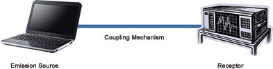
In fact, many devices can behave as both receptors and emitters of electromagnetic interference. Communication systems like cell phones, for example, utilise both transmitters and receivers, which can emit an EMI signal that has the potential to not only affect other systems, it can also couple back onto itself.
The means by which EMI is coupled between pieces of equipment (Figure 2) are generalised as being either conducted or radiated in nature, or a combination of both. Conduction refers to a type of transmission whereby a signal is conveyed along a lead wire or cable that is leaving and entering a piece of equipment. EMI within this classification is usually considered to be low-frequency in nature, with 30 MHz generally acknowledged as the upper limit.
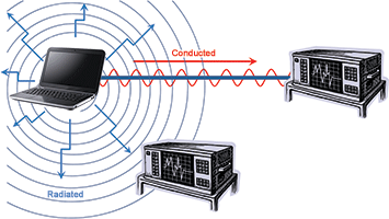
Radiated emissions are higher-frequency signals coupled from one device to another without a direct electrical connection. The transmission mechanism is wireless and capable of travelling through non-conductive materials such as air, space, plastic and insulators.
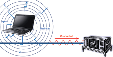
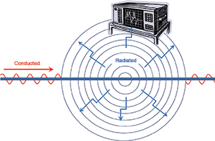
In situations where a combination of both conducted and radiated emissions are at work, signal, power and ground cables can act like receiving or transmitting antennas, as illustrated in Figures 3 and 4.
EMI suppression
Depending on the means of propagation, unwanted electromagnetic signals can generally be suppressed through the use of proper shielding, filtering and grounding techniques, or a combination thereof (Figure 5).
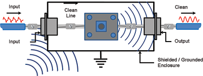
Where the designer is dealing with radiated emissions, suitable shielding, through the use of tightly sealed metal or metallised housings, will help to mitigate transmission of unwanted EMI into and out of the enclosure. Unfortunately, this approach is not considered practical, as some openings are obviously needed to accommodate conductors that connect to external sources and loads.
In this case, the selection of a suitable electrical filter, placed in line with these conductors and properly grounded at the housing access or egress point, will not only provide for further shielding, but will also allow for elimination of conducted EMI. A combination of these two methodologies and use of a low-resistance connection to ground, will normally provide adequate isolation, eliminate unintended electromagnetic signals, both radiated and conducted, and allow all associated equipment to operate as intended.
Compliance testing
Electromagnetic compatibility or EMC is established through the performance of emissions testing which identifies the frequency and amplitude of EMI generated by a device, and/or immunity testing, which verifies the performance of a device or system when subjected to known levels of EMI.
Emissions are measured by connecting a line impedance stabilisation network (LISN), a current probe or an antenna to an EMI receiver, scanning the desired frequency range and measuring the amplitude of the signals detected. This procedure would act much in the same way as the ‘scan’ button on an FM radio.
Immunity/susceptibility testing, by comparison, connects the LISN, a current probe or antenna to an RF amplifier and injects a signal into the system being evaluated. For this analysis, the equipment still scans for EMI signals, but now the intention is to monitor the performance of the device under test while subjected to the energy and determine what sort of response, if any, the equipment exhibits.
Emissions and immunity testing are further broken down into four basic EMC tests: radiated emissions, conducted emissions, radiated immunity and conducted immunity. Radiated tests utilise an antenna in the test setup, whereas conducted tests deal specifically with wires and cables and are easy to identify as there are no antennas used.
Real world considerations
Typical RF emissions limits are 100 dB or lower than typical RF immunity requirements. In other words, if all electronic devices in a given environment are limited to such low levels of emissions, then why are these same devices required to handle such high levels of immunity?
The short answer is that electronic devices must be designed to operate in the presence of both radio transmitters and radio receivers (see Figure 6). Radio transmitters generate relatively high levels of energy so that the transmitter can be detected by radio receivers that can be miles away.
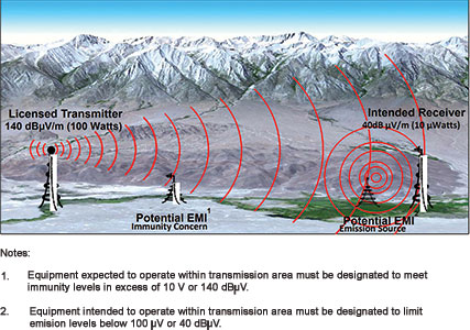
Conversely, radio receivers are designed to detect extremely low levels of energy because of the great distances involved with radio transmissions. Immunity test levels simulate the energy levels that electronic devices will be exposed to when they are operated in close proximity to radio transmitters. Emission limits reflect the maximum energy levels that electronic devices should emit when they are operated in close proximity to radio receivers, so as not to interfere with the radio receiver’s operation or significantly reduce its operating range.
Standards and specifications
From a global perspective, most governments have established very specific rules and regulations related to the control of EMI and the majority take it a step further by stipulating guidelines for testing systems in an attempt to ensure an acceptable level of EMC.
The International Electrotechnical Commission (IEC), via its International Special Committee on Radio Interference (CISPR), has created globally accepted EMI and EMC rules. South Africa adopts these CISPR standards under its own set of SANS (South African National Standards) designations. The South African Bureau of Standards (SABS) is authorised to issue a certificate of compliance for products that pass applicable EMC testing at an accredited laboratory. ICASA (Independent Communications Authority of South Africa) is tasked with enforcing a regulation requiring any EMI-propagating product sold in the country to be suitably certified.
Conclusion
Electromagnetic compatibility is becoming more and more significant, especially in light of continually evolving EMC legislation, and as such has become an important aspect in the design of electronic equipment and systems. A lack of understanding when it comes to possible sources of electromagnetic interference and failure to address those situations, can potentially lead to unwanted and potentially hazardous results in critical applications.
| Tel: | +27 11 726 6758 |
| Email: | hreispty@iafrica.com |
| www: | www.eispty.co.za |
| Articles: | More information and articles about Electronic Industry Supplies |


© Technews Publishing (Pty) Ltd | All Rights Reserved
 printer friendly version