


Manual cleaning of soldering residues can be inconsistent across the industry. After rework or second-stage assembly, manual cleaning is difficult to guarantee that all residues have been removed and no contamination exists that may impact function or reliability.
Most problems occur when a customer decides that the no-clean process he has been accepting is not as clean as he would like and stipulates cleaning. Often this change in the process is not well thought through. This results in failure or cosmetically disappointing board assemblies.
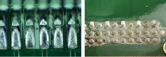
To achieve and demonstrate the best possible result, engineers and production staff need to work as a team to define a process where cleaning material and flux residues are compatible (Figure 1 shows a possible consequence of not doing so). Finally, to achieve consistency, training members of staff, engineers, contract assemblers and possibly customers to complete the operation is very important. Design engineers should consider the circuit design, defining critical areas for special attention to maintain their electrical performance.
Ideally, disposable gloves should be worn when working with soldering and cleaning materials in a rework area. Handle the board by its edges wherever possible, even when using gloves. If cotton gloves are used to reduce perspiration, they should be changed regularly. Remember that ESD-control wrist straps are worn on the skin, not over gloves, so fit the strap before the gloves.
During rework or manual assembly, applying flux or paste to pads or terminations on components (particularly area array packages) is best practice as it will leave minimum residues to remove from the PCB. Flooding the board surface, using a brush or dispensing bottle to apply liquid flux or gel should be avoided during rework – it is just more mess to clean.
After rework, modification or second-stage assembly, cleaning may need to be considered or specifically required. Ideally a no-clean flux, gel or solder paste which has been tested on site should be used to avoid the need to clean selected areas. This would be agreed in advance with a customer - often customers don’t like dirty PCBs.
If manual cleaning is conducted, every effort should be made to use materials or application methods that result in the minimum residues from both flux and cleaning process in a defined process sequence. The cleaning material used must be compatible with the boards, components and most importantly, the residues to be removed.
The remaining residues from the soldering materials must be totally soluble in the cleaning material, and this requires pre-production trials and some form of reliability assessment like SIR (surface insulation resistance) or ion chromatography. ROSE testing is not adequate for confirming reliability. ROSE testing is a process control test often used as part of an evaluation process; it is not used to assess reliability of a product.
Suppliers of the cleaning chemistry will normally outline the best methods of cleaning residues from PCBs, or help you develop a procedure like the one outlined in our online webinar presentation.
Manual cleaning methods should apply the minimum solution to clean the board, components and under the components where possible. Any brushes should not shed any bristles, and can be natural fibre or alternative to avoid static generation or mechanical abrasion to the solder joints or solder mask.
There is a benefit with some synthetic white bristles as they also show up excess residues due to poor housekeeping. Any brushes used should be changed regularly. A combination solvent and a self-priming brush to control the amount of solution used, as well as providing the mechanical agitation, can be beneficial. The methods do rely on the skills of the staff in using the tools and they are the best people to help define the process.
A board assembly should ideally be lifted and angled (See Figure 3) so that the cleaning material can run off the board on to an absorbent sheet. The direction of cleaning should be selected to minimise the cleaning solution running on to other parts of the board. It is also possible to use a dry/wet wipe around the component termination to be cleaned to capture any run-off from residues.
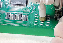
Placing a dry or wet wipe over the component area while brushing the terminations through the wipe can also work well (see Figure 4). The flux and cleaner is absorbed by the wipe and controls the run-off during cleaning and blow-off. The wipes selected will need to be more robust to avoid breakup during cleaning, but still be absorbent.

When cleaning and rinsing is complete and the flux residues appear to be removed, a non-shredding wet wipe can remove any cleaning drying/evaporation marks separately. Drying marks can be seen on the surface of the solder mask, which is another reason to specify the type of mask at the design stage - most engineers never do. Take care around component terminations to avoid damage as wipes can snag and leave fibres on the board, particularly on conventional through-hole leads.
It is best to repeat the operation with fresh cleaner as a final rinse, and wipe the surface using one of the methods outlined. Cleaning is best performed after the soldering or rework process. The residues tend to be more soluble this way than leaving them for a long period of time after soldering.
Finally, use a low-pressure air gun to remove any cleaner from under or around components and connectors, placing a dry/wet wipe on the opposite sides of the component to capture any fluid displaced by the air flow. Again, angle the board so any remaining contamination drains to the edge of the board and the wipe away from other components. If fluid is still present it may require a final wipe with a lint-free cloth.
It is good practice to allow the board assembly to stand vertically on a rack after cleaning, if possible with the reworked area at the bottom. The board assembly may be placed in a low temperature, air circulated oven. It would also be normal practice to bake board assemblies before any conformal coating process is applied, but this would be at a higher temperature as recommended by the coating supplier.
Never rush the cleaning, drying and conformal coating steps as some cleaners will react with coatings, preventing them from fully curing. The coating will fall off and in the worst case produce corrosion. Make sure that any wipes and old brushes are placed in the appropriate disposal container. In the case of brushes make sure they are cleaned after use to prevent them being clogged with residues or use disposable brushes.
Further information on cleaning is available in IPC-CH-65B, the Cleaning Handbook and IPC specifications like IPC 7711-7721. As with any assembly process, training staff in good practice, the materials and methods to be used and inspection for residues after manual cleaning is recommended. Any training should be included in any rework or hand soldering course and be recorded on staff records. Training should also be conducted for test engineers who often do touch-up.
Any manual cleaning must be developed as a process on the shop floor and not just adopted historically. The material compatibility, cleaning methods and acceptance criteria are defined by engineers with the support of production staff to assess the practical methods. Production
staff are invaluable to test and try new methods and materials, or when flux or paste are changed.
Just like any other process, engineer it or you will just have failures and customer returns.
For more information visit www.bobwillis.co.uk


© Technews Publishing (Pty) Ltd | All Rights Reserved
 printer friendly version