


As new and more complex surface mount component packages continue to evolve, and the mass, component density and cost per unit area of printed circuit board assemblies continue to increase, the process of safely and efficiently removing and replacing the components presents a challenge to even the most skilled rework technicians. If removed components are to be re-used, it becomes an even greater challenge.
The selection of appropriate tools and use of proven techniques are crucial in successfully addressing increasingly difficult rework issues. Various rework tools and techniques are available and should be chosen based upon a careful evaluation of the specific application. Before final tool and process determinations can be made, a number of component, printed circuit board, tool, profile and process parameters and requirements must be considered.
There are four basic preparatory areas that must be considered:
1. Component characteristics analysis.
2. PCB characteristics analysis.
3. Tool selection.
4. Heating cycle profile development.
Once the above steps have been completed, the seven basic rework process phases may be undertaken:
1. Board pre-heat.
2. Reflow of component solder.
3. Vacuum removal of the component.
4. Cleaning and preparation of the PCB pads.
5. Screening of solder paste.
6. Placement and reflow of the new component.
7. Inspection of the solder joints.
Basic preparatory areas
1. Component characteristics analysis
After the component to be removed has been tagged and marked for location and pin orientation, the exact component package configuration and specifications must be determined. In order to properly assess the application, develop an acceptable thermal rework profile and select the proper equipment, the component package type, size, number and type of leads, lead pitch, maximum process temperature and degree of metallisation needed.
These specifications, along with rework recommendations, are listed on the component data sheet provided by the manufacturer. Most packages are made of epoxy or ceramic, two materials with significantly different thermal characteristics. Metallisation, such as leads, terminations and heatsinks, can also have a significant impact upon the thermodynamics of the device and the eventual thermal profile of the rework process.
Surface mount components are generally categorised as two-terminal, three-terminal or four-or-more-terminal devices. The two- and three-terminal devices are by far the simplest and are generally discrete (one circuit element) components. In many cases, they can be manually removed using a soldering iron or set of heated tweezers, particularly if the components are not to be re-used.
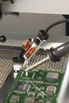
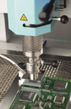
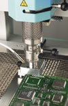
Since direct contact (conduction) is more likely to result in board or component damage, hot gas (convection) is often used to remove and replace even the simplest surface mount components. Hot gas systems are generally referred to as hot air systems even though inert gases, such as nitrogen, are often used. Many hot air systems incorporate integrated vacuum for safe, automatic lift-off of the component after reflow. Manual tools, or a separate vacuum pipette system, may also be used.
The component package configuration and the proximity of adjacent components often determine the most appropriate method of component removal. Although multi-leaded, complex components, such as SOICs, PLCCs and QFPs, can be removed by direct contact methods utilising special tool nozzles, development and utilisation of a convective hot air profile is generally recommended and considered to be a safer, more repeatable method of removal.
Some component packages, such as MLFs (micro lead frame), QFNs (quad flat no lead), DFNs (dual flat no lead), SONs (small outline no lead), LGAs (land grid array) and BGAs (ball grid array) are low stand-off or leadless devices that must be removed using hot air, or a combination of conductive (hot tool), convective (hot air) and infrared heating methods.
2. PCB characteristics analysis
The rework equipment and method chosen for a particular application also depend upon the characteristics of the PCB. Component density, number of layers, size, mass, PCB thickness, copper thickness, number and extent of ground and power planes, solder alloy and board type must be considered.
A high-mass, densely populated, multi-layer FR4 (fire retardant fibre-glass epoxy laminate) board appears as a considerable heatsink to a rework heat source. Ceramic boards heat faster and more uniformly than boards made of glass epoxy materials. Mylar flex assemblies are more heat sensitive and fragile.
PCBs are moisture sensitive devices, and in order to remove moisture that has been absorbed by the material, boards often require pre-baking at or above 100°C prior to rework or assembly. Out-gassing of moisture during subsequent operations can cause delaminating of the PCB, voids in the solder and popcorning of components.
PCB moisture sensitivity becomes an even greater issue with the higher process temperatures necessary for lead free solder. Pre-baking increases oxidation on the PCB pads and can have a negative impact on the soldering process.
Component density must also be considered when selecting a rework process. A heavily populated board increases the overall thermal mass of the PCB. Also, adjacent components can often interfere with tooling and experience damage during the rework process. Unless precautions are taken, they can possibly reflow, become skewed, or even be blown from the board during hot air removal of the defective component.
Protective shields, covers and dams are available to prevent reflow of adjacent components. Kapton or polyimide tape can also be used. The solder alloy used on the PCB assembly must be identified prior to rework.
Lead-free alloys have higher melting points, require more heat and dictate a tighter process window. Finally, the PCB is inspected to determine if components are encapsulated with epoxy or a conformal coating. If so, the encapsulating material must be identified and removed from the defective component prior to rework.
3. Tool selection
After the component and PCB have been thoroughly evaluated, the rework method and equipment must be selected. The method and equipment are chosen based upon the estimated complexity and difficulty of the application as determined by the component and PCB assessments, the estimated temperature and amount of thermal energy required, and the availability of appropriate equipment.
Soldering irons, desoldering tools, hot air tools, bottom side pre-heaters and heated tweezers, along with an assortment of hand tools and board fixture equipment, are used for conductive and convective SMT rework. Variable temperature, electronically controlled, high wattage tools are needed for most applications.
Solder paste syringes, dispenser, and solder print stencils are also used in the rework process. Manual hot air tools are available providing 700 Watts of heat and up to 50 litres per minute of hot air flow. Complete multi-channel manual rework systems are available that provide simultaneous operation of an assortment of rework tools, including various wattage soldering, desoldering, hot tweezers, bottom side preheaters and hot air tools.
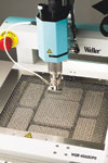
Automated and semi-automated rework systems that incorporate a hot air tool, a vacuum pickup and placement head, and a convective or infrared bottom side pre-heater, are available and are used for indirect non-contact removal.
Pre-heating of the PCB is critical, particularly for medium- to high-mass assemblies that can heatsink significant energy from a soldering iron tip or hot air tool. Pre-heating minimises the thermal stress imposed upon the PCB and components, enhances the wetting process by activating flux and removing oxides and surface films, permits lower nozzle temperatures for reflow, and reduces the rework cycle time.
Removing components using top side, focused hot air, or direct contact heating only, can result in lifted pads and a warped or twisted PCB. Bottom side pre-heat also provides the increased process control necessary for lead-free applications.
A good automated, computer controlled, hot air rework system will provide variable temperature, ESD-safe hot air, variable air flow, numerous nozzle configurations, bottom side infrared and/or convective pre-heat, split optics for precision alignment and placement, manual and automatic operation, vacuum for component pickup, simplified ‘Teach Mode’ and multiple zone profile development, a separate or integrated board holder/tool stand with accessories, and control software for remote operation from a PC.
4. Heating cycle profile development
Complex multi-lead or no-lead surface mount components on a multi-layer PCB generally require use of a hot air rework system with bottom side pre-heat for successful removal and replacement. In order to provide a safe, repeatable and efficient process, a thermal profile is developed for each component being reworked. A profile is a temperature signature of the component throughout the heating cycle.
The settings of the hot air equipment (nozzle temperature, air flow rate and time), the temperature settings of the bottom side pre-heater, and the fixture position or distance of the PCB and component relative to the hot air tool and pre-heater, determine the profile.
The solder alloy used on the PCB assembly must also be known prior to rework. Lead-free and tin/lead applications require different temperature settings and profiles. Recommended profiles are provided by solder manufacturers for the various alloys.
A rework profile consists of a minimum of four stages: a pre-heat stage, a soak stage, a reflow stage and a cooling stage. Profiling requires some type of thermal management and monitoring system to provide temperature control and feedback throughout the development process. A separate or built-in data acquisition system is recommended to provide sufficient temperature data collection, charting and analysis for profile development.
Rework systems often provide built-in feedback for the hot air nozzle and the bottom side pre-heater, but these temperatures generally reflect higher set values and do not represent actual temperatures of the component and PCB being reworked.
For proper temperature monitoring and profiling, thermocouple probes are attached to the component (either beneath the component, beneath the component leads, or directly to the top of the component), the top side of the PCB (pad or via next to the component being removed) and the bottom side of the PCB (pad or via beneath the component being removed) for monitoring the process temperatures of the critical rework elements.
Even if a single component is being removed without a profile being developed, it is important to attach probes and monitor process temperatures to prevent component and/or PCB damage. The thermocouple probes are made with very fine wire to minimise loading effects and are attached using high-temperature solder or Kapton, polyimide or aluminium foil tape. High-temperature epoxy is also used for probe attachment. Special attention must be given to low-temperature components and connectors.
The heating cycle can be stopped if monitored temperatures approach maximum allowable limits. Thermocouple probe placement is critical for accurate temperature monitoring. It must be secure, and the sensing portion of the probe must be in direct contact with the component or metallised portion of the PCB.
Most hot air rework systems have at least one thermocouple input for monitoring process temperature and a method of storing and recalling profiles. If multiple thermocouple inputs are needed for monitoring on a single-input system, a separate multi-input data acquisition system or additional temperature monitoring instruments must be used.
Component profiles and process recommendations are generally provided on the manufacturer’s component data sheet. In order to minimise thermal stress and possible component short- or long-term damage, it is recommended to maintain a temperature ramp rate (increase over time) between 2°C per second and 4°C per second.
Basic rework processes
1. Board pre-heat
Once a profile is established, the hot air rework cycle can begin without concern for damage to the component or PCB. If the same or a similar component is to be reworked on a number of identical PCB assemblies, the profile provides a safe, repeatable process.
2. Reflow of component solder
Flux is applied to the component prior to the desoldering cycle to remove oxidation and enhance solder reflow. Using a specific profile, the component is heated until solder reflow occurs.
3. Vacuum removal of the component
Once reflow occurs, the component is removed using manual hand tools such as tweezers or vacuum pickup pen, or the component is automatically lifted from the board using the vacuum system integrated into many of today’s rework systems.
4. Cleaning and preparation of the PCB pads
After component removal, the pads are cleaned of excess solder and prepped for the new component. Solder may be removed from the pads using desolder braid and a soldering iron, a soldering iron and manual desolder vacuum pump, or desoldering iron with integrated automatic vacuum.
Again, flux is applied prior to removing the excess solder from the pads. After the pads are cleaned of solder, flux cleaner or similar solvents, brushes and lint-free wipes are used to thoroughly clean the pads and the rework area of the PCB.
5. Screening of solder paste
If solder paste is used, the print stencil must be aligned to the pads and the paste printed prior to component placement. Solder paste may also be dispensed onto the pads prior to placement using various dispensing methods and systems.
Due to the increased board densities and use of MLF and QFN devices, solder paste is often screen printed onto the component instead of onto the PCB as part of the rework process. This alternative method of printing generally requires special stencils and fixtures.
6. Placement and reflow of new component
Once the area is cleaned, and if solder paste is not being screened or dispensed onto the PCB pads, the new component is properly oriented, aligned and placed into position. The new component is aligned and placed either manually (be sure ESD precautions are followed) or automatically. Manual placement is performed using manual tweezers, needle probes, vacuum pickup tools and proper magnification.
Proper lighting and magnification are critical to successful rework. Many rework systems provide automatic alignment and placement. Some systems provide precision mechanical alignment, while other systems incorporate a camera with split optics and precision x, y and theta adjustments to provide coincident alignment of the component to the pads.
The component package configuration and/or the lead pitch of the component determine the minimum requirements for placement. A precise positioning system is required to place low stand-off or leadless components with hidden joints.
Once a new multi-leaded component is in place, the method used to solder the leads depends upon the type of solder being used. A soldering iron is generally used to solder a component into place using wire cored solder. A hot air tool is used if solder paste is being used.
If a soldering iron is used, the component is fluxed and held in place while the corner leads are tack soldered. After the corners are tacked, the remaining leads are soldered using point-to-point or multi-point soldering methods.
Leadless or BGA components must be reworked using a hot air system. If a hot air system is used to solder the new component in place, the same profile previously developed to remove the defective component is used.
7. Inspection of the solder joints
At this point, a thorough cleaning of the circuit board is required for some applications. Detailed inspection of the solder joints is the final step of the rework process.
| Tel: | +27 11 704 3020 |
| Fax: | 086 555 0111 |
| Email: | [email protected] |
| www: | www.ama-sa.co.za |
| Articles: | More information and articles about Allan McKinnon & Associates |


© Technews Publishing (Pty) Ltd | All Rights Reserved
 printer friendly version