


The biggest challenges hyperscale companies face today involve:
• Global thermal management.
• Rising power consumption.
• Hardware density: not enough room to upscale hardware capacity.
There is a technological solution to all three challenges: components based on photonic integrated circuits (PIC). PICs are the cornerstone for building high-speed communication networks enabled by modern high-speed optical transceivers. These optoelectronic devices combine passive and active optical functions within a single monolithic structure (chip) which is then integrated into the transceiver.
PICs are the disruptive technology behind the new wave of optical transceivers. Manufacturers are replacing electronic subcomponents with photonic-based ones since they boast advantages such as high integration and compactness, outstanding power consumption savings and enhanced thermal management. The next generation of optical pluggables relies on PIC technology to achieve enhanced integration and low power consumption. The first commercial samples arrived in 2019.
This application note reviews:
• Challenges to the transceiver industry when it comes to validating thousands of units at different manufacturing stages.
• Best practices for testing and qualification of PIC-based optical pluggables.
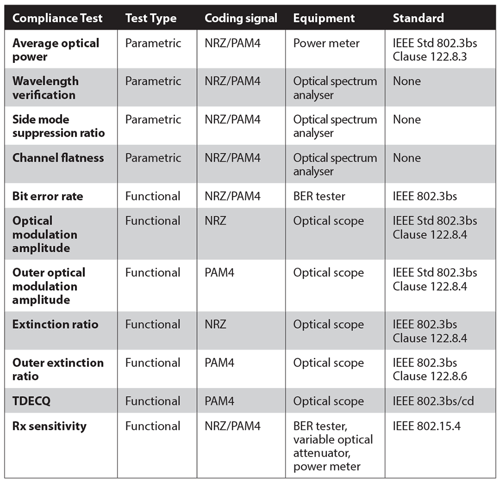 Table 1. Optoelectronic compliance tests for transceivers.
Compliance testing of transceivers on the production floor
Recent market reports forecast solid growth for silicon-photonics based transceivers. Demand for transceivers is booming and vendors are under pressure to manufacture and validate thousands of units every day.
However, PIC manufacturers currently face major challenges in both R&D; and mass production of transceivers and other non-telecom applications. Solutions that can provide rapid, simple, reliable and accurate evaluation of pluggables are therefore critical in keeping pace with an evolving and demanding landscape. Electrical and optical parameters must be tested during the manufacturing process to guarantee compliance with specifications and industry standards, and manufacturers cannot afford to omit either type of test.
Compliance tests can be divided into two main types:
• Parametric tests, which are carried out during transceiver design and integration. These tests are mainly focused on the performance of the transmitter optical subassembly (TOSA) and receiver optical subassembly (ROSA) components.
• Functional tests for quality control purposes. These tests are usually carried out during the final stages of production.
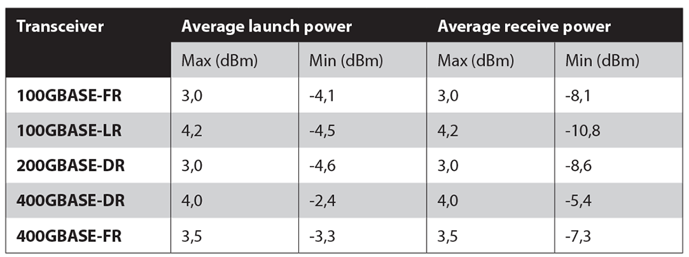 Table 2. Average optical power recommended in IEEE Std 802.3bs Clause 122.8.3.
Average optical power (AOP)
The AOP measured at the transmitter and at the receiver is crucial to regular communication in transceivers. It is regularly validated using a power meter. Only when both transmitted and received optical power are within the recommended thresholds can the transmission distance (reach) of the modules be ensured. Optical modules with different wavelengths, transmission rates and transmission distances have different transmitted and received optical power, as can be seen in Table 2.
Wavelength verification
This test involves measurement of the central wavelength of the laser emission. For modules that include multiple channels, such as CDWM transceivers, spectral verification is performed for each of the peaks of emission. Required wavelength accuracy for the tester is ±20 pm.
There are two ways to perform this kind of test:
1. Use a wavemeter, which is directly linked to the output of the TOSA.
2. Replace the wavemeter with an optical spectrum analyser (OSA). However, few OSAs on the market can meet the required wavelength accuracy standard, and those that do achieve high-wavelength accuracy using spectral calibration with an altered reference source.
Side-mode suppression ratio (SMSR)
The side-mode suppression ratio test is also performed using an OSA. The SMSR is the power difference between the main peak power and the first side modes on the left and the right.
Calculating an accurate SMSR value calls for OSA power accuracy of ±0,5 dBm. The minimum value for a successful test is SMSR ≥ 30 dBm. It’s also common to perform this test while the temperature of the optical module ranges between -20 to 80°C.
Channel flatness
Channel flatness is the power difference between two continuous emission peaks. This parameter is calculated using an OSA’s spectral evaluation.
The channel flatness is required for multi-channel transceivers (e.g., a CWDM sample that presents four channels spaced by 20 nanometres). The pass verdict is obtained when the maximum power difference is ≤ 4 dBm.
Bit error rate (BER) test
Bit error rate is the parameter that best describes the overall health of a communication system. It is the chief indicator of component or network performance.
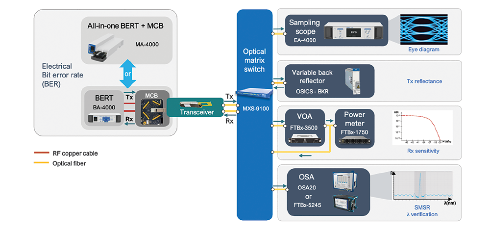
BER tests on the production floor aim to verify the real rate that can be generated and detected for a transceiver. The setup to perform a BER test on a transceiver (shown in Figure 1) enables observation of the bit error rate tester linked to the module compliance board (MCB) that receives electrical signals in the transceiver. Sometimes the module compliance board is embedded in the chassis of the BER tester.
The bit error rate test consists of:
1. Generating and sending a determining pattern of data that passes through the transceiver.
2. Looping the optical signal back.
3. Comparing the received pattern against the expected pattern to calculate the bit error rate.
A healthy test value is < 10–12 (see Figure 1).
Optical modulation amplitude (OMA)
A healthy bit error rate value is generally achieved when there is a noticeable power difference between the logical zero and the logical one level in the eye diagram. The OMA defines the maximum and minimum optical amplitude at the transmitter, and it’s measured with an optical scope. The simplest setup involves connecting the line side of the transceiver directly to the optical oscilloscope.
IEEE gives great importance to the OMA because it provides quantified information about the quality of the transmission. The OMA is then a standardised parameter and the value depends on the type of transceiver.
Extinction ratio (ER)
Extinction ratio uses a ratio of the power used to transmit logic level one to the power used to transmit logic level zero. An ER of PAM4 signals is the ratio between the average signal level three power and signal level zero power. ER is determined by performing a statistical analysis from the eye diagram. It determines whether the optical power of the transmitter meets standards requirements. ER for a highspeed transceiver must be a value between 3 and 4 dB.
TDECQ
Transmitter and dispersion eye closure quaternary (TDECQ) determines whether a transmitter’s performance meets the basic requirements for transmitting PAM4 signals. TDECQ is deduced from the eye diagram using an optical oscilloscope.
TDECQ is a new metric for PAM4 devices, a replacement for traditional NRZ masks tests, that provides high accuracy based on statistical methodologies. The TDECQ target value for 400G PAM4 components is typically 3,4 dB.
Receiver sensitivity
The receiver sensitivity test, which characterises receiver performance, is probably the most important functional test. It provides the minimal received optical signal power at the Rx to achieve certain BER values in a back-to-back configuration. These parameters show the quality of the receiver design i.e., the better receiver sensitivity, the better assisted performance in terms of longer transmission distances.
The typical setup to run a receiver sensitivity test is performed using an electrical BER tester linked to the MCB, where the transceiver under test is hosted. On the optical side, the signal goes to both an optical attenuator and a power meter. The objective is to degrade the BER by introducing attenuation that simulates impairments in the network or component. The BER value is then plotted as a function of the power. While this test is running, it is a good idea to run other tests such as an OMA receiver-side test.
Conclusion
End-to-end transceiver qualification calls for a comprehensive range of high-end optical and electrical testers designed to deliver quick, reliable evaluations. To help transceiver vendors ensure compliance throughout the transceiver lifecycle, EXFO has recently launched a new range of solutions which includes electrical BER testers, optical sampling scopes and clock data recovery sources.
| Tel: | +27 12 349 1341 |
| Email: | [email protected], [email protected] |
| www: | www.lambdatest.co.za |
| Articles: | More information and articles about Lambda Test |


© Technews Publishing (Pty) Ltd | All Rights Reserved
 printer friendly version