


Today’s evaluation board-based prototyping for an RF design takes a significant amount of engineering time and resources, and the result may still lack the performance the final system will have once built on a single board.
Prototyping RF designs with the X-Microwave modular system can dramatically reduce the time and resources needed to test an RF signal chain by enabling clean, modifiable, near-PCB prototypes through 60 GHz to be built and tested in a single afternoon. This article provides an overview of the X-Microwave platform and its advantages, as well as a step-by-step guide to getting started.
The typical prototyping experience for an RF design includes purchasing an evaluation (eval) board for each of the components in the signal chain, and using RF cabling to string the boards together, creating a rough approximation of how the signal chain would perform were it built on a single production PCB after being properly laid out. This method can accrue significant insertion loss from long eval board PCB traces and extensive cabling and connectors. The resulting prototype can also be frustrating and time consuming to bring online because of the specific voltage requirements of each eval board. It’s also not uncommon for an RF part to require multiple voltages with specific power rail sequencing, which if violated could destroy the component. Just the power and RF wires alone can create a rat’s nest, and if any board needs digital control, things are further complicated. If the whole system doesn’t work the first time you turn it on, debugging quickly degrades into an exercise in patience and perseverance. Prototyping is a headache well known in the RF engineering world – the solution to faster, easier, and more accurate prototypes is X-Microwave.
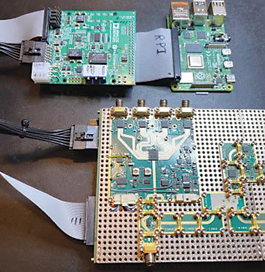
X-Microwave is a modular RF prototyping platform that allows easily modifiable signal chains to be built up in under an hour without any specialised tools. These signal chains are composed of X-Microwave blocks – connectable single-IC RF boards – and there are parts in the ecosystem that support frequencies up to 60 GHz. The RF connections – solderless contacts secured by hex screws – are robust and simple to install. The signal chain is much easier to power and digitally control than eval boards, requiring a single 12 V DC supply to the control board and either a Raspberry Pi, FPGA, or other driver of your choice. The X-Microwave modular design enables fast signal chain edits, reduces debug time significantly, and keeps the prototype compact, clean, and portable.
The X-Microwave solution
Engineers can use X-Microwave to achieve the performance of an end-design single PCB with the prototyping speed and modifiability of evaluation boards. An X-Microwave prototype is made up of small, single-IC blocks that can be strung together to create a signal chain. From amplifiers to mixers, switches, PLLs, and VCOs, the X-Microwave ecosystem has thousands of RF blocks available to support a variety of full signal chains. Each individual RF block comprises a single RF IC, either a packaged part or die, with the surrounding passives required for optimal function and matching.
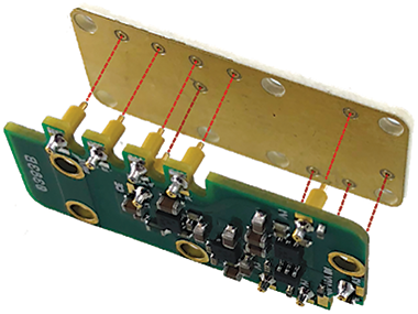
X-Microwave takes special care with the RF layout and design to ensure the device performs as close to datasheet specifications as possible. On each RF block, grounded coplanar waveguide traces run from the IC to launches on the edges of the block. RF connections are made from these launches to the neighbouring block using solderless ground-signal-ground (GSG) interconnects. These interconnects closely resemble continuous PCB traces, allowing the X-Microwave prototype’s overall performance to represent final system performance much more accurately than a large connection of eval boards.
X-Microwave’s GSG jumper connections each have an insertion loss of just fractions of a decibel, and as the number of components in the signal chain increases and more interconnects are needed, the difference in insertion loss between X-Microwave and SMA-linked evaluation boards becomes even more pronounced.
The RF blocks are mounted together on a protoplate, with SMA probe blocks attached to the ends of the signal chain to get the RF signal into and out of the board. X-Microwave also has walls and lids available to enclose RF blocks, allowing you to simulate cavity effects.
X-Microwave prototypes behave significantly more like the end design than a string of evaluation boards, and this difference becomes more pronounced as the number of components in the RF chain increases. By proving the design with an X-Microwave prototype, you can be much more confident in your evaluation, minimising PCB iterations and accelerating the development process.
| Tel: | +27 11 923 9600 |
| Email: | info@arrow.altech.co.za |
| www: | www.altronarrow.com |
| Articles: | More information and articles about Altron Arrow |


© Technews Publishing (Pty) Ltd | All Rights Reserved
 printer friendly version