


Noise in electrical circuits is typically the enemy, and any self-respecting circuit should output as little noise as possible. Nevertheless, there are cases where a well-characterised source of noise with no other signal is entirely the desired output. Circuit characterisation is such a case. The outputs of many circuits can be characterised by sweeping the input signal across a range of frequencies and observing the response of the design. Input sweeps can be composed of discrete input frequencies or a swept sine. Extremely low frequency sine waves (below 10 Hz) are difficult to produce cleanly.
A processor, DAC and some complex, precise filtering, can produce relatively clean sine waves, but for each frequency step, the system must settle, making slow work of sequential full sweeps featuring many frequencies. Testing fewer discrete frequencies can be faster, but increases the risk of skipping over critical frequencies where high Q phenomena reside.
A white noise generator is simpler and faster than a swept sine wave because it effectively produces all frequencies at the same time with the same amplitude. Imposing white noise at the input of a device under test (DUT) can quickly produce an overview of the frequency response over an entire frequency range. In this case, there is no need for expensive or complex swept sine wave generators. Simply connect the DUT output to a spectrum analyser and watch. Using more averaging and longer acquisition times produces a more accurate output response across the frequency range of interest.
The expected response of the DUT to white noise is frequency-shaped noise. Using white noise in this fashion can quickly expose unexpected behaviour such as weird frequency spurs, strange harmonics and undesirable frequency response artifacts. Furthermore, a white noise generator allows a careful engineer to test a tester. Lab equipment that measures frequency response should produce a flat noise profile when measuring a known flat white noise generator.
On the practical side, a white noise generator is easy to use, small enough for compact lab setups, portable for field measurements, and inexpensive. Quality signal generators with myriad settings are attractively versatile. However, versatility can hamper quick frequency response measurements. A well-designed white noise generator requires no controls, yet produces a fully predictable output.
Noisy discussion
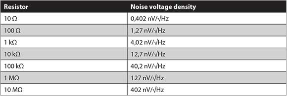
Resistor thermal noise, sometimes called Johnson noise or Nyquist noise, arises from thermal agitation of charge carriers inside a resistor. This noise is approximately white, with nearly Gaussian distribution. In electrical terms, the noise voltage density is given by VNOISE=√(4kBTR), where kB is the Boltzmann’s constant, T is the temperature in Kelvin, and R is the resistance.
Noise voltage arises from the random movement of charges flowing through the basic resistance, a sort of R×INOISE. Table 1 shows examples at 20°C. A 10 MΩ resistor, then, represents a 402Gizmo layout.
nV/√Hz wideband voltage noise source in series with the nominal resistance.
A gained up resistor-derived noise source is fairly stable as a lab test noise source, as R and T variations affect noise only by square root. For instance, a change of 6°C from 20°C is a change of 293 kΩ to 299 kΩ. Because noise density is directly proportional to the square root of temperature, a change of 6°C temperature leads to a relatively small 1% noise density change. Similarly, with resistance, a 2% resistance change leads to a 1% noise density change.
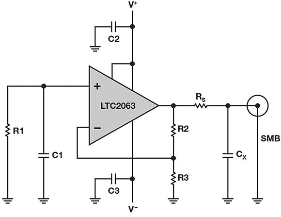
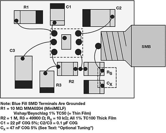
Consider Figure 1: a 10 MΩ resistor R1 generates white, Gaussian noise at the positive terminal of an op-amp. Resistors R2 and R3 gain the noise voltage to the output. Capacitor C1 filters out chopper amplifier charge glitches. The output is a 10 µV/√Hz white noise signal. Gain (1 + R2/R3) is high- 21 V/V in this example. Even if R2 is high (1 MΩ), the noise from R2 compared to the gained up R1 noise is inconsequential.
An amplifier for the circuit must have sufficiently low input-referred voltage noise so as to let R1 dominate as the noise source. The reason is that the resistor noise should dominate the overall accuracy of the circuit, not the amplifier. An amplifier for the circuit must have sufficiently low input-referred current noise to avoid (IN × R2) to approach (R1 noise × gain) for the same reason.
How much amplifier voltage noise is acceptable?
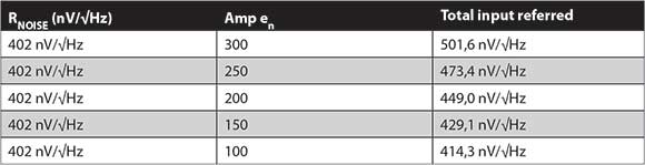
Table 2 shows the increase in noise from adding independent sources. A change from 402 nV/√Hz to 502 nV/√Hz is only 1,9 dB in log volts, or 0,96 power dB. With op-amp noise ~50% of the resistor noise, a 5% uncertainty in op-amp VNOISE changes the output noise density by only 1%.
A white noise generator could employ only an op-amp without a noise-generating resistor. Such an op-amp must exhibit a flat noise profile at its input. However, the noise voltage is often not accurately defined and has a large spread over production, voltage and temperature. Other white noise circuits may operate based on a Zener diode with far less predictable characteristics. Finding an optimal Zener diode for stable noise with µA of current can be difficult, however, particularly at low voltage (less than 5 V).
Some high-end white noise generators are based on a long pseudorandom binary sequence (PRBS) and special filters. Using a small controller and DAC may be adequate; however, making sure that the DAC does not produce settling glitches, harmonics or intermodulation products is something for experienced engineers. Additionally, choosing the most appropriate PRBS sequence adds complexity and uncertainty.
Low power zero-drift solution
Two design goals dominate this project:
• An easy to use white noise generator must be portable; that is, battery-powered, which means micropower electronics.
• The generator must provide uniform noise output even at low frequencies – below 0,1 Hz and beyond.
Considering the preceding noise discussion and these critical constraints, the LTC2063 low-power, zero-drift op-amp fits the bill.
The noise voltage of a 10 MΩ resistor is 402 nV/√Hz; the LTC2063’s is roughly half. The noise current of a 10 MΩ resistor is 40 fA/√Hz; the LTC2063’s is less than half. The LTC2063 fits neatly into a battery application inasmuch as its supply current is 1,4 µA typical, and total supply can go down to 1,7 V (rated at 1,8 V). Since low frequency measurements by definition require long settling times, this generator must remain powered by a battery for extended periods of time.
The noise density of the LTC2063 input is roughly 200 nV/√Hz, and noise is predictable and flat over the frequency range (within ±0,5 dB).
Assuming that the LTC2063’s noise is 50% of thermal noise and op-amp voltage noise changes 5%, output noise density changes only 1%.
Zero-drift op-amps do not have zero 1/f noise by design. Some are better than others and, especially for current noise, it is more common that the wideband specification is wrong or that 1/f noise is much higher than suggested in the data sheet. For some zero-drift op-amps, the data sheet noise plot does not go down to the mHz frequency region, possibly masking 1/f noise.
A chopper stabilised op-amp could be a solution to keep the noise flat at very low frequency. That said, the high frequency noise bump and switching noise must not spoil the performance. The data shown here supports the use of the LTC2063 in the face of these challenges.
Circuit description
The thin film R1 (Vishay/Beyschlag MMA0204 10 MΩ) generates most of the noise. The MMA0204 is one of few 10 MΩ options to combine high quality with low cost. In principle, R1 could be any 10 MΩ, as signal current is very small, so 1/f noise can be neglected.
It is best to avoid low-cost thick film chips of questionable accuracy or stability for the primary element of this generator. For best accuracy and long-term stability, R2, R3 or RS could be 0,1% thin film – for example, TE CPF0603. C2/C3 could be one of most dielectrics; C0G can be used to guarantee low leakage current.
Implementation details
Loop area R1/C1/R3 should be minimised for best EMI rejection. Additionally, R1/C1 should be very well shielded from electrical fields, which will be discussed further in the EMI considerations section. Although not critical, R1 should be shielded from large temperature changes. With good EMI shielding, thermal shielding is often adequate.
The LTC2063 rail-to-rail input voltage transition region of the VCM range should be avoided, as crossover may result in higher, less stable noise. For best results, use at least 1,1 V for V+ with the input at 0 common mode.
Note that RS of 10 kΩ may seem high, but the micropower LTC2063 presents a high output impedance; even 10 kΩ does not fully decouple the LTC2063 from load capacitance at its output. For this white noise generator circuit, some output capacitance that leads to peaking can be a design feature rather than a hazard.
The output sees 10 kΩ RS and a 50 nF CX to ground. This capacitor CX will interact with the LTC2063 circuit, resulting in some peaking in the frequency response. This peaking can be used to extend the flat bandwidth of the generator, in much the same way that port holes in loudspeakers attempt to expand the low end. A high-Z load is assumed (>100 kΩ), as a lower-Z load would significantly reduce the output level, and may also affect peaking.
The remainder of this article can be read online at www.dataweek.co.za/+K4999, and covers optional tuning, measurements, EMI considerations and limitations of this design.
For more information contact Conrad Coetzee, Arrow Altech Distribution, +27 11 923 9600, ccoetzee@arrow.altech.co.za, www.arrow.altech.co.za
| Tel: | +27 11 923 9600 |
| Email: | info@arrow.altech.co.za |
| www: | www.altronarrow.com |
| Articles: | More information and articles about Altron Arrow |


© Technews Publishing (Pty) Ltd | All Rights Reserved
 printer friendly version