


The vast variety of RF coaxial connectors and cable available often makes it a difficult task for an engineer to specify or select the correct part for a particular application.
Often, not much thought is given to essential factors and components, and this can be devastating to the performance of the system. RF systems comprise a number of items eg, antennas, attenuators, amplifiers, couplers, power meters, RF generators, etc, and it is not uncommon for much thought to go into the high-tech devices while RF coaxial connectors and cable are often treated as an afterthought.
RF coaxial connectors and cable provide a vital link within the communications, EMC testing, commercial and military, and not to mention the measurement fields. Although there are a variety of RF coaxial connectors, they are characterised by a few key parameters. The most obvious factor is the size, followed by power handling and frequency range. To ensure maximum power transfer, the impedance of the connector should match the source load. These characteristics, along with connector durability and cost, must be considered in light of the specific application. This article offers suggestions and insight into selecting the best connector and cable system for a project.
Intermodulation in RF coaxial connectors
The increased demand from the mobile communication industry to provide greater channel capacity, coupled with increased sensitivity of receivers, has exposed a condition within RF coaxial connectors referred to as intermodulation distortion. Intermodulation products are generated when two or more frequencies are applied to a non-linear transmission element. A non-linear device is produced when the signal applied does not have a proportional ratio between current and voltage at the same time.
These mixed frequencies can cause disruption in communication systems or measuring equipment if several carrier frequencies with a high intensity have the same transmission path as weak receiving signals ie, mobile phones. The occurrence of intermodulation in passive components is caused by very small non-linearities of the conducting parts. The affected elements include connectors, cables, filters and antennas.
The reasons for non-linearity in passive devices are unsuitable contact geometry, use of magnetic materials (ie, steel, nickel), contaminated or oxidised contacts, dissimilar contact base materials and microscopic field discharging effects.
Potential causes of intermodulation within RF coaxial connectors include:
* Contaminated plating solution.
* Insufficient plating thickness.
* Corrosion.
* Dissimilar metals in intimate contact.
* Magnetic materials in the signal path.
* Low contact pressure.
* Less than 360° contact.
* Poor surface finish.
* Debris and dust within the connector.
* Convoluted signal path.
The presence of any of the above elements within a system will negatively impact the performance of the entire system. For this reason, all components in a transmission path must be selected to suit the system requirements. It is therefore recommended for critical applications that the largest conducting surface possible is chosen to avoid high current densities. The connector selected must provide for a defined mechanical stop of the outer conductor. The use of a threaded coupling interface ensures that the interface is correctly engaged and for this reason the 7/16 and N ranges are preferred due to their increased power capabilities and particular suitability for low intermodulation applications. TNC, 4.1/9.5 and SMA type interfaces could also be considered.
To ensure the long-term electrical and mechanical stability of the assembly, it is essential that this operation is carried out correctly. Cable or panel mount connectors should have a full 360° electrical contact to the outer conductor – the solder/clamp termination method is preferred, since it offers improved intermodulation stability over the crimp termination variants. A crimp, by its nature, can only provide a multiple-point contact (rather than 360° contact) and also causes variability in the positioning of the electrical contact during dynamic testing.
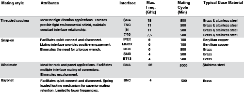
Table 1 compares the attributes of several connector interfaces.
Selecting an RF coaxial cable
The selection of RF coaxial cable is as important as the type of connector or termination technique used. For high-power applications with high intermodulation requirements, corrugated copper tubes or semi rigid lines without a steel centre conductor are recommended. In the majority of cases, flexible coaxial cable is considered unsuitable for these applications due to their braided screening. In these cases the cable manufacturer’s specification should be referred to.
Proper selection of an RF coaxial cable for specific assembly requirements is critical to ensure overall performance and integration into a larger component system. Key considerations in proper selection of an RF coaxial cable include:
* Frequency – The required frequency of the application defines the available choice of cable.
* Impedance – Determined by the ratio of an inner conductor to the outer in a dielectric medium. The impedance of cable and connector must match 50 or 75 Ω.
* Power handling – Overall system failure can be prevented with the selection of specified power ratings that the coaxial cable can handle.
* Shielding efficacy – This varies among coaxial cables depending upon the materials and shielding employed in the design. RF signal ‘leaking’ from the cable can in some applications cause interference or cross-talk between signals in the transmission line.
* Attenuation – Measured in dB/metre, the insertion loss will determine how much of the input power is lost through the transmission line. Where power requirements are critical or with long lengths of cable, insertion loss can be a limiting factor.
* Bending radius – A function of the size of the cable and construction of the centre conductor, solid or stranded. The dielectric type and number of shields will impact overall flexibility.
Reflections in coaxial connectors
All connectors produce signal reflections at high frequencies, due to minor differences between the connector impedance and that of the overall system. These irregularities have either inductive or capacitive behaviour depending on the operating frequency and the degradation of performance at higher frequencies. Unmatched impedances can also be caused by a combination of internal dimension changes and tolerances, material and termination techniques. Different mating interfaces can also affect the overall system performance. This reflection performance is commonly expressed as return-loss (a), voltage standing wave ratio (VSWR) and reflection coefficient r. with all three being related to each other mathematically.
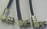
Due to the increased accuracy of cutting and solder termination of semi-rigid cables, smaller impedance irregularities are achieved when compared with flexible coaxial cables. Connector styles also affect reflection ie, straight connectors generally produce better performance than 90° versions. Reflection performance can therefore vary within the same connector series, depending on style and cable.
Connector types and characteristics
BNC
A miniature version of the Type C, the acronym BNC stands for Bayonet Neill Concelman of Bell Labs. Probably the most widely used within the test and measurement field, this connector was developed in the 1950s and is commonly found on oscilloscopes, receivers, analysers and similar lab equipment. All 50 Ω and 75 Ω connectors are intermateable with each other without restrictions. Applications include computers/LANs, instrumentation, test and measurement, medical equipment and broadcast (75 Ω).
TNC
TNC stands for Threaded Neill Concelman, and this connector is simply a threaded BNC version. It provides a more secure connection and thus reduces vibration found in the BNC connector. TNC connectors are miniature weatherproof connectors with a constant 50 Ω impedance and operate in the 0–11 GHz frequency range. They are an ideal choice for use in cellular mobile communications and test and measurement equipment. TNC connectors are widely used in airframe, aerospace and radar applications where extreme vibration is a factor.
The TNC connector range is suitable for the standard ranges of flexible and semi-rigid cables and is also available as a PCB mounted version. All 50 Ω and 75 Ω connectors are intermateable.
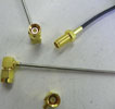
SMA
Developed in the 1960s by Omni-Spectra, this connector offers a mode-free solution to 18 GHz and is very popular in high-frequency, low-power applications. Two ranges of SMA connector are available – the standard range is manufactured with brass bodies and the special range from stainless steel or beryllium copper.
The main features are high mechanical strength, high durability and low VSWR.
SMA connectors are commonly used as interconnects on RF boards, microwave filters and attenuators. Precision versions extend the frequency up to 26,5 GHz. Although the SMA will mate with the 2,92 mm, 3,5 mm, APC3.5 and K type connectors, it is not recommended as slight dimensional differences may result in connector damage. Special torque wrenches are used to achieve the correct torque.
N type
The N connector was the first coaxial connector capable of microwave performance and was invented in the 1940s by and named for Paul Neill of Bell Labs. The N connector is the most widely used and most common RF connector in use around the world today. It is rugged, relatively inexpensive and the standard version is capable of mode-free operation to 11 GHz.
Precision type N connectors push the upper frequency limit to 18 GHz. They are ideal for use in all systems where very good RF and mechanical performance are critical, whether at low or high frequencies. Both 50 Ohm and 75 Ohm versions are available, the latter being commonly used in the CATV industry.
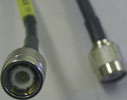
7-16 DIN
The Deutsches Institut für Normung, aka the German National Standards Organisation, developed the 7/16 connectors – hence the ‘DIN’ designation. The 7/16 threaded interface connectors are designed for low intermodulation and VSWR applications in medium- to high-power transmission systems. Several styles within this range are supplied with sealing rings and are suitable for outdoor applications. These connectors are suitable for the standard range of flexible, semi-rigid and corrugated cables.
The numerical part of the name refers to the size of the inner and outer conductors. The 7/16 uses an M29 x 1,5 threaded coupling nut. Common applications include antennas, base-station connections, RF cables, satcom and lightning protection systems. Power and frequency are limited to approximately 1500 W average at 7,5 GHz with the standard version. More advanced versions are available with FLH dielectrics.
| Tel: | +27 11 314 4101 |
| Email: | [email protected] |
| www: | www.dscoms.com |
| Articles: | More information and articles about DS Communications |


© Technews Publishing (Pty) Ltd | All Rights Reserved
 printer friendly version