


All across the globe, the landscape of high-rise buildings and municipal water towers is changing. Once barren, these locations are now home to core macrocellular network installations, specifically cell towers and antennas.
By using high-power radio frequency (RF) signals, macrocell sites allow wireless service providers to deliver voice, text and broadband communications over large geographic areas.
Unfortunately, as traffic increases, coverage radius decreases. This means that even though cells can be upgraded, coverage cannot be expanded. Essentially, the best way to feed bandwidth to the entire wireless infrastructure is to increase fibre connectivity and penetration.
The HetNet reality
In the stone age of cellular phones, back when voice communication was the only offering, network design focused on coverage, not capacity. Today’s phones have morphed into portable, application-oriented, Internet-enabled computers, greatly increasing the strain on network capacity.
Unfortunately, adding new macro sites, microcells and picocells simply won’t cut it. A better way to augment the macro layer is by adding low-power nodes like femtocells, remote radio heads/units (RRH/RRU) and distributed antenna systems (DAS). This enhanced macrocellular network is called a ‘heterogeneous network’ or HetNet.
Small cells
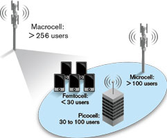
From humble beginnings, small cells are now flourishing, and can be divided into three primary types:
A femtocell is a small base station designed for residential use.
A picocell is a base station larger than a femtocell, but smaller than a microcell. It can typically handle 10 to 60 simultaneous callers, although it can service over 100 in some cases. Picocells are deployed both indoors and outdoors.
A microcell is a base station larger than a picocell, but with a smaller coverage area and capacity than a macrocell. These stations are often used to support cellular service in large buildings, conference centres and shopping malls. In high-rise buildings, they feed the DAS to extend coverage to multiple floors.
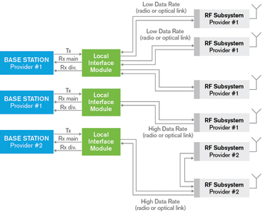
Remote radio head
A remote radio head is a single, outdoor unit with RF front-end functionality only. It connects to the baseband processing part of a distributed base station via a point-to-point, bidirectional, analog or digital interconnection link. However, other links are possible, namely star, ring and daisy chain.
Analog links, due to their linearity requirements, require a highly linear system to maintain their spectral emission properties when transporting low-level RF composite signals. Although optical fibre interconnection cables offer high linearity, they require very expensive optical lasers and drivers.
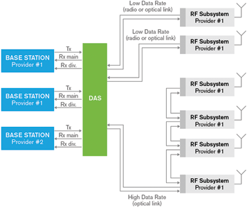
Distributed antenna systems
Today, DAS is considered a multiple airlink, multiple frequency band and multiple wireless service provider (WSP) system, that is mostly fibre-optic or coax based. Designed to distribute cellular signals throughout buildings, active DAS equipment uses head-end and remote units to get as much as possible out of the expensive part (i.e., the base station).
Since a DAS enables the independent operation of multiple frequency bands and protocols across a single access network, multiple operator network sharing is supported. This ability is the secret to its success
DAS versus RRH
DAS and RRH architectures are similar in a number of ways. They both centralise the baseband processing of the base station at one location and use strategically located radio modules to satisfy coverage or capacity requirements. They both use optical fibre to run very high data rates and high capacity backhaul needs at baseband-unit locations. They also both excel in areas where ultra-high density nodes are required.
DAS can be considered an evolution over RRH in the sense that DAS can transport data relevant to multiple RF carriers and multiple WSPs. However, this also means DAS demands a much higher overall link data rate.
On the other hand, RRH can also be considered an evolution over DAS. While DAS extends the coverage of legacy base stations, RRH offers cost-reducing base station design. Another major difference is that unlike DAS, which uses RF-optical converters as add-on modules, RRH does not require converters because it already uses optical technology.
Fibre-to-the-cell-site
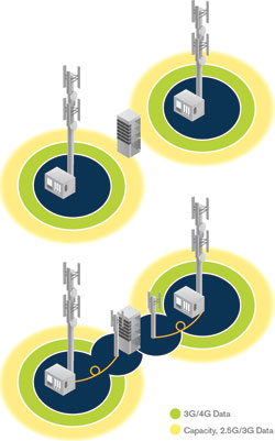
By bringing high data rate to the radio/antenna, fibre-optic links deliver the promises made by mobile broadband. Increasing broadband capacity means growing the wireless network, which decreases the cell radius. Therefore, feeding bandwidth to the entire wireless infrastructure means increasing fibre connectivity and penetration. Essentially, more wireless means better and deeper wireline.
Two standards are used to carry traffic from the base station’s radio equipment controller (REC) to the radio equipment over fibre: CPRI (Common Public Radio Interface) and OBSAI (Open Base Station Architecture Initiative); CPRI is used predominantly.
The purpose of any fibre-optic network is to perform high-speed, error-free data transmission. The best testing practices at each phase are therefore required to achieve the expected data rate and reliability, while minimising costly and time-consuming troubleshooting efforts by locating dirty/damaged connectors, questionable splices and other faulty components.
In the case of DAS, since a single system can transport data from multiple carriers, the fibre infrastructure has to be installed, qualified, tested and certified by a third party (e.g. antenna or network owner, subcontractor). Moreover, a birth certificate and proof of proper installation are often required.
Budget loss
When designing a fibre-optic network, it is important to evaluate the acceptable loss. Loss in a fibre-optic cable includes intrinsic attenuation and extrinsic discontinuities, such as connectors and splices. Link loss is wavelength-dependent, measured in decibels per kilometre (dB/km) and used to calculate the overall budget loss.
Proper transmission can be ensured by controlling network power loss with respect to the link-loss specifications. This is done by establishing a total end-to-end budget loss with sufficient margins, while reducing back-reflections to a minimum. This is especially true for high-power analog RF video signals (normally at 1550 nm) emitted by extremely narrowband lasers, since strong back-reflections degrade the quality of the signal transmission.
To adequately characterise budget loss, the following key parameters are generally considered:
* Transmitter: launch power, temperature and ageing.
* Fibre connections: connectors and splices.
* Cable: fibre loss and temperature effects.
* Receiver: detector sensitivity.
* Other: safety margin and repairs.
When one of these variables fails to meet specifications, network performance can be greatly affected. In fact, some degradations will lead to network failure. Therefore, calculating budget loss should be a priority in any deployment. It should also be mandatory to verify that the class of system selected is compatible with the topology that is deployed.
Fibre connection
For a system to work properly, network elements must be interconnected. At the moment, there are two main ways to interconnect all network elements: connectors and splices. Maintaining them in good condition is essential to maximising performance and minimising loss.
Since single-mode fibres have very small cores – typically 9 to 10 μm in diameter – a single particle of dust or smoke can block the transmission area and increase loss. This means that damaged or dirty connectors can lead to incorrect test results, high insertion loss (IL) or optical return loss (ORL) and permanent damage to the link (in the case of high power transmission).
In the case of splices, fibres that are poorly aligned (cores not perfectly in line) lead to coupling loss. Another source of coupling loss is the difference in optical properties between connected fibres. If the spliced fibres have different optical properties, such as different core or cladding diameters, then coupling losses may increase. This is termed ‘core mismatch’.
Macrobends
A macrobend is a curvature in an optical fibre whose radius is a few centimetres, typically found in fibre organisers and at (or near) patch panels. They are caused by the mishandling of cables or by mechanical stresses from the environment.
In many fibre-optic telecommunication systems, macrobends will occasionally increase link loss to a point where it exceeds the system’s loss budget.
Furthermore, it is also widely accepted that induced attenuation increases with wavelength, due to a wider modal distribution and more power in the cladding. Since replacing transmitters and receivers is expensive, local maintenance crews are called upon to locate and repair these macrobends.
Fibre testing
Adequate testing will help locate problematic splices, dirty or damaged connectors and other faulty components at installation, which will minimise costly and time consuming troubleshooting efforts. Choosing the best testing practices is the key to ensuring a successful and easy-to-maintain network.
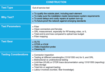
Testing during the construction phase is key to qualifying the network and generating documentation for future reference, ensuring it meets transmission system requirements (standards) and avoiding delays and repairs at system turn-up. These test protocols are summarised in Table 1.
CPRI/OBSAI testing
After the fibre test, a CPRI/OBSAI test should be performed. This validates that actual traffic can be carried from the base station to the tower. It also lets technicians check that the power level is within specifications, and that the transmission and receive rates are acceptable. This is done by running a bit error rate (BER) test and making sure that no errors or alarms are received in both directions.
Documentation
When the network is down, productivity is lost and customers are unhappy, which leads to lost revenue. Good documentation will not only simplify the internal transfer of knowledge, it will also help an external team quickly understand the network and minimise the mean time to repair (MTTR), thus lowering the cost to operator and customer.
However, a large volume of documentation can be lost when networks are built by contractors or subcontractors. It is therefore essential for them to save the test results of the work done in the field. Some measurements do not require post-processing, but most will require analysis and diagnosis (e.g. test reports, birth certificates).
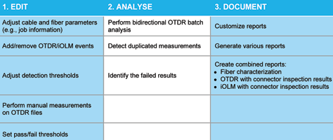
The three logical data post-processing steps – edit, analyse and document – are summarised in Table 2.
Conclusion
A compact base station architecture is the best option. However, its transport connectivity relies on traditional backhaul techniques, which run at significantly lower data rates than the streams on fibre-cabled DAS/RRH systems. This explains why wireless backhaul and fibre are both excellent transport solutions for tomorrow’s infrastructures and why HetNet is being deployed today.
For more information contact Chris Nel, Lambda Test Equipment, +27 (0)12 349 1341, [email protected], www.lambdatest.co.za
| Tel: | +27 12 349 1341 |
| Email: | [email protected], [email protected] |
| www: | www.lambdatest.co.za |
| Articles: | More information and articles about Lambda Test |


© Technews Publishing (Pty) Ltd | All Rights Reserved
 printer friendly version