


The first half of this article was published in the 25 February 2015 issue of Dataweek.
Core sensor
Whether simple bandpass filtering is adopted to process vibration signals, or more complex but more flexible digitisation techniques are preferred, the core sensor for either approach can be a MEMS accelerometer. While many tri-axial MEMS accelerometers support direct connection with most embedded processors, capturing the best available level of performance might require single- or dual-axis solutions that have analog outputs.
For example, the high-performance ADXL001 wideband iMEMS accelerometer leverages its 22 kHz resonance to provide one of the widest available bandwidths, but it is only available as a single-axis, analog-output device. Analog outputs can enable a quick interface in systems that have an available analog-to-digital channel, but the present trend of development seems to favour those sensors that have digital interfaces.
The core sensor’s frequency response and measurement range determine the maximum vibration frequency and amplitude that it can support before saturating the output. Saturation degrades the spectral response, creating spurious content that can cause false alarms, even when the saturation frequency does not interfere with a frequency of interest. The measurement range and frequency response are related by:

where D is the physical displacement, ω is the vibration frequency, and A is the acceleration.
While the frequency response and measurement range place upper boundaries on the sensor’s response, its noise and linearity place limits on the resolution. The noise will establish the lower limit of the vibration that will cause a response in the output, while the linearity will determine how much false harmonic content is generated by a vibration signal.
Analog filter
The analog filter limits the signal content to one Nyquist zone, which represents one half of the sample rate in the example system. Even when the filter cut-off frequency is within the Nyquist zone, it is impossible to have infinite rejection of higher-frequency components, which can still fold back into the passband.
For a system monitoring only the first Nyquist zone, this fold-back behaviour can create false failures and distort the view of the vibration content at a particular frequency.
Windowing
Time-coherent sampling is often not practical in vibration sensing applications, as non-zero sample values at the start and end of the time record result in large spectral leakage, which can degrade the FFT resolution. Applying a window function before calculating the FFT can help manage the spectral leakage. The best window function is dependent on the actual signal, but in general, the trade-offs include process loss, spectral leakage, lobe location and lobe levels.
Fast Fourier Transform (FFT)
The FFT is an efficient algorithm for analysing discrete time data. The process transforms a time record into a discrete spectral record, where each sample represents a discrete frequency segment of the Nyquist zone. The total number of output samples is equal to the number of samples in the original time record, which in most cases represents a number in the binomial series (1, 2, 4, 8 … ).
Spectral data has both magnitude and phase information, which can be represented in either rectangular or polar form. When in rectangular form, one half of the FFT bins contains magnitude information, while the other half contains phase information. When in polar form, one half of the FFT bins contains the real result, while the other half contains the imaginary result.
In some cases, both magnitude and phase information are helpful, but the magnitude/frequency relationship often contains enough information for detecting key changes. For devices that offer only magnitude results, the number of FFT bins is equal to one half of the samples in the original time-domain record.
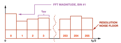
The FFT bin width equals the sample rate divided by the total number of records. In a way, each FFT bin is like an individual bandpass filter in the time domain. Figure 5 provides an example of an actual MEMS vibration sensor which samples at 20 480 samples per second (SPS) and starts with 512-point records. In this case, the sensor only provides the magnitude information, so the total number of bins is 256 and the bin width is equal to 40 Hz (20480/512).
The bin width is important because it establishes the frequency resolution as the frequency shift from one bin to an adjacent bin, and because it determines the total noise the bin will contain. The total noise (rms) is equal to the product of the noise density (~240 μG/√Hz) and the square root of the bin width (√40 Hz), or ~1,5 mG rms.
For low-frequency applications, where noise tends to have the most influence on resolving vibration, a decimation filter prior to the FFT process can help improve the frequency and magnitude resolution without requiring a change in the ADC’s sample frequency. Decimating the 20 480 SPS sample rate by a factor of 256 enhances the frequency resolution by a factor of 256 while reducing the noise by a factor of 16.
Spectral alarms
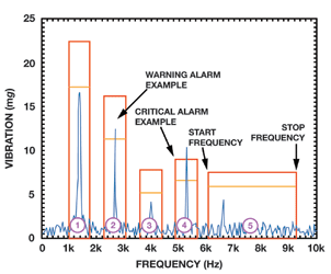
One of the key advantages of using an FFT is that it enables simple application of spectral alarms. Figure 6 provides an example that includes five independent spectral alarms that monitor the natural frequency in the machine (#1), its harmonics (#2, #3 and #4) and the wideband content (#5). The warning and critical levels correspond to the levels in the machine health vibration vs. time profile.
The start and stop frequencies complete the process variable definition represented by this relationship. When using an embedded processor, the spectral alarm definition variables (start/stop frequencies, warning/critical alarm levels) can be in configurable register locations that use digital codes for configuration. Using the same scale factors and bin numbering scheme can greatly simplify this process.
Record management
One of the key functions associated with process variable relationships is record management. Storing FFT records from different stages of each machine’s lifetime enables analysis of a variety of behaviours that may lead to a wear-out curve that contributes to maintenance and safety planning.
In addition to compiling historical vibration data, some will find value in capturing condition data associated with parameters such as power supply, temperature, date, time, sample rate, alarm settings and filtering.
Interface
The interface depends on the existing infrastructure in a particular plant. In some cases, industrial cable-ready com-munication standards such as Ethernet or RS-485 are readily available, so the interface between a smart sensor and the communication system might be an embedded processor.
In other cases, that same embedded processor might be used to interface the smart sensor with an existing wireless protocol, such as Wi-Fi, ZigBee or a system-specific standard. Some smart sensors, such as the ADIS16000 wireless gateway node for remote sensors and the ADIS16229, come with a ready-to-deploy wireless interface that is available through common embedded interfaces such as SPI or I2C.
Conclusion
Inertial MEMS technology is ushering in a new era of vibration monitoring and enabling a wider user base for this type of instrumentation. Performance, packaging, and familiarity may contribute to continued use of piezoelectric technology, but vibration monitoring is clearly growing and evolving.
Through functional integration and ease of adoption, MEMS devices are gaining increasing attention in new vibration monitoring applications. Convenience, through advanced signal processing at the point of sensing, reduces the monitoring burden to a simple state (normal, warning, critical) for most situations. In addition, remote data access through convenient communication channelsis creating new applications for vibration monitoring instruments.
Future advances in key performance metrics (noise, bandwidth and dynamic range) and the high level of functional integration will help this trend to continue in the near future.
For more information contact Kevin Godfrey, Arrow Altech Distribution, +27 (0)11 923 9600, [email protected], www.arrow.altech.co.za
| Tel: | +27 11 923 9600 |
| Email: | [email protected] |
| www: | www.altronarrow.com |
| Articles: | More information and articles about Altron Arrow |


© Technews Publishing (Pty) Ltd | All Rights Reserved
 printer friendly version