While DC-DC conversion circuitry has matured to the point that there are ‘cookbook’ design aids as well as software to help, selecting the right power inductor is a critical aspect of converter design. This requires a good understanding of inductor performance and of how desired in-circuit performance relates to the information available in supplier data sheets.

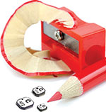
Inductors that can be used in DC-DC converters come in a wide variety of shapes and sizes (Figure 1). In order to compare types and choose the optimal part for the application, a designer must rely on correctly understanding published specifications.
Inductor performance can be described by relatively few numbers. A typical data sheet excerpt for a surface-mount power inductor intended for DC-DC converters is shown in Table 1.
Inductance
Per Table 1, the inductance (L) is the main parameter that provides the desired circuit function and is the first parameter to be calculated in most design procedures. It is calculated to provide a certain minimum amount of energy storage (or volt-microsecond capacity) and to reduce output current ripple. Using less than the calculated inductance causes increased AC ripple on the DC output. Using much greater or much lower inductance may force the converter to change between continuous and discontinuous modes of operation.
Because it is not practical for a data sheet to show performance for all possible sets of operating conditions, it is important to have some understanding of how the ratings would change with different operating conditions.
Tolerance
Fortunately, most DC-DC converter applications do not require extremely tight tolerance inductors to achieve these goals. It is, as with most components, cost-effective to choose standard tolerance parts, and most converter requirements allow this. The inductor in Table 1 is shown specified at ±20%, which is suitable for most converter applications.
Test conditions
These are critical, and designers need to pay special attention to voltage, wave shape and test frequency. For example, most catalogue inductance ratings are based on ‘small’ sinusoidal voltages, and the use of sinusoidal voltage is a standard instrumentation test condition.
With regard to frequency, most power inductors do not vary dramatically between 20 kHz and 500 kHz, so a rating based on 100 kHz is quite often used and suitable. However, inductance eventually decreases as frequency increases. As switching frequencies increase to 500 kHz, 1 MHz and above, it becomes more important to consider ratings based on the actual application frequency.
DC resistance (DCR)
This is based strictly on the wire diameter and length and is specified as a ‘max’ in the catalogue but can also be specified as nominal with a tolerance. DCR varies with temperature, so it is important that the DCR rating also notes the ambient test temperature.
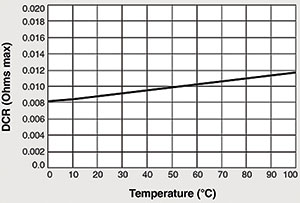
The temperature coefficient of resistance for copper is approximately +0,4% per degree Celsius. So the part shown rated at 0,009 Ω max would have to have a corresponding rating of 0,011 Ω max at 85°C — only a 2 mΩ difference in this case, but a total change of about 25%. The expected DCR versus temperature is shown in Figure 2.

AC resistance
This is not commonly shown on inductor data sheets and is not typically a concern unless either the operating frequency or the AC component of the current is large with respect to the DC component.
When trying to minimise the size of the component, the designer should try to select the part with the largest possible resistance. Typically, to reduce the DCR means having to use larger wire and probably a larger overall size. So optimising the DCR selection means a trade-off of power efficiency, allowable voltage drop across the component, and component size.
Self-resonant frequency (SRF)
Every inductor winding has some associated distributed capacitance, which, along with the inductance, forms a parallel resonant tank circuit with a natural self-resonant frequency. For most converters, it is best to operate the inductors at frequencies well below the SRF. This is usually shown in the inductor data as a ‘typical’ value.
Current rating
This is perhaps the rating that causes the most difficulty when specifying a power inductor. Current through a DC-DC converter inductor is always changing throughout the switching cycle and may change from cycle to cycle depending on converter operation, including temporary transients or spikes due to abrupt load or line changes. This gives a constantly changing current value with a sometimes very high peak-to-average ratio.
It is the peak-to-average ratio that makes specification difficult. Look for an inductor that has two current ratings: one to deal with possible core saturation from the peak current and one to address the heating that can occur due to the average current.
Saturation current (Isat)
One effect of current through an inductor is core saturation. Frequently, DC-DC converters have current wave shapes with a DC component. The DC current through an inductor biases the core and can cause it to become saturated with magnetic flux. The designer needs to understand that when this occurs, the inductance drops and the component no longer functions as an inductor.
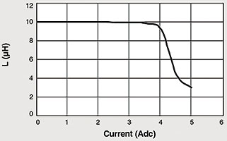
A typical inductance versus current curve for a gapped ferrite core is shown in Figure 3. It can be seen that this curve has a ‘knee’ as the inductor moves into the saturation region. Definition of where saturation begins is, therefore, somewhat arbitrary and must be defined. In the example of Table 1, saturation is defined at the point at which the inductance drops by 10%. Definitions in the range of 10% to 20% are common, but it should be noted that some inductor catalogues might use figures of 50% inductance drop. This increases the current rating but may be misleading as far as the usable range of current is concerned.

While there is more to be said on this topic, suffice it to say that it is typically desirable to operate with current peaks near the saturation rating because this allows the smallest possible inductor to be chosen.
RMS current (Irms)
The second major effect of current is component self-heating. The Irms is used to give a measure of how much average current can continuously flow through the part while producing less than some specified temperature rise. In this case, the data sheets usually provide a rating based on application of DC or low-frequency AC current, so this does not include heating that may occur due to skin effect or other high-frequency effects. The current rating may be shown for a single temperature rise point as in the example, or some suppliers provide helpful graphs of temperature rise versus current or factors that can be used to calculate temperature rise for any current.
Temperature rise due to self-heating may cause the inductor to be at a temperature higher than the rated range. This is normally acceptable provided that the insulation ratings are not exceeded. As with other parameters, it is important to know the inductor temperature rise so that this can be traded off with other parameters when making design choices. If lower temperature rise is desired, a larger size component is most likely the answer.
Conclusion
It can be seen that inductors for DC-DC converters can be described by a small number of parameters. However, each rating may be thought of as a ‘snapshot’ based on one set of operating conditions that may need to be augmented to completely describe expected performance in application conditions.
For more information contact Andrew Hutton, RF Design, +27 (0)21 555 8400, andrew@rfdesign.co.za, www.rfdesign.co.za
| Tel: | +27 21 555 8400 |
| Email: | sales@rfdesign.co.za |
| www: | www.rfdesign.co.za |
| Articles: | More information and articles about RF Design |

© Technews Publishing (Pty) Ltd | All Rights Reserved