


Commissioning a new installation is necessary as it establishes a baseline of performance for customer acceptance and follow-on maintenance.It is important not only for photovoltaic (PV) system performance, but also for the longevity of equipment, safety, ROI, and warranties. Fluke is experiencing increasing demand for high-precision handheld devices which can measure PV systems.
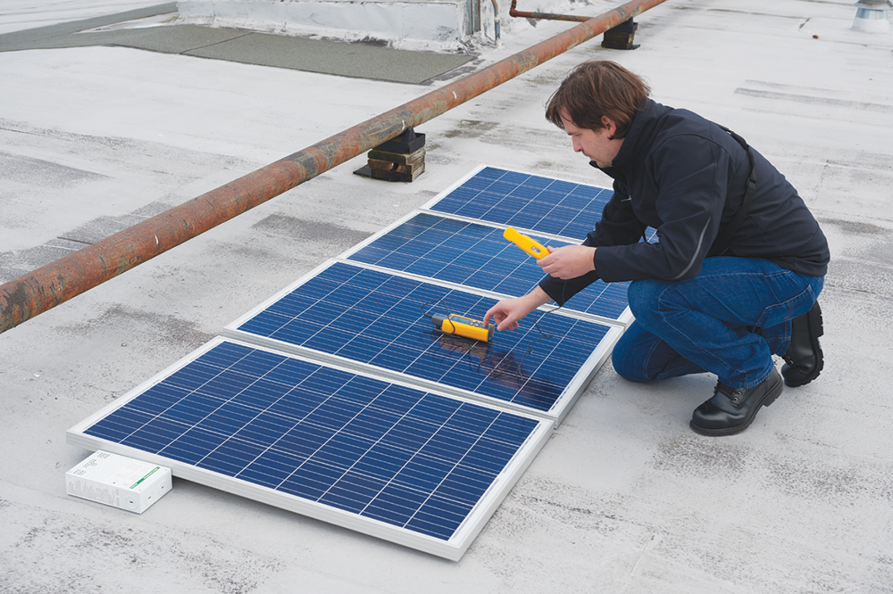 Figure 1. Commissioning a PV system for maximum performance.
Step 1: Photovoltaic system design and production
Step 1 is to determine the solar resource and take into account any shading that may occur on the panels. The solar resource is measured in peak sun hours, which is the number of hours the installation achieves 1000 W/m2/day. A good solar resource can deliver 6000 W/m2, or six peak sun hours. The Fluke IRR-1 Solar Irradiance Meter can be used to determine the actual solar irradiance and shading at the site to develop a baseline.
Let’s consider a 10 kW PV array. The expected average daily production may be calculated by multiplying the 10 kW array by six peak sun hours and then by 0,85 (15% derating due to power losses in wiring and inverter). This array should produce 51 kWh per day. Or put another way, the average South African household which uses 36 kWh per day would require a PV installation of 7 kW.
Step 2: Measuring PV performance
Once the system is installed, its electrical characteristics and the actual power output of the array can be measured to make sure it’s operating as designed. The performance of a PV array is based on its current-voltage (IV) curve. Not only does an inverter convert DC to AC, but it also maximises its power output by maintaining the current and voltage at which the highest power is being produced.
The short circuit current (Isc) is the maximum current from a cell. The open circuit voltage (Voc) is the maximum voltage from a cell measured when the circuit is open. The point at which the module produces the most power is called the maximum power point (mpp).
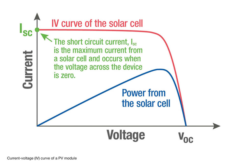 Figure 2. Current-voltage (IV) curve of a PV module.
Voc can be measured by using the Fluke 393 FC CAT III Solar Clamp to determine the voltage between the positive and negative terminals. The 393 FC is CAT III 1500 V/CAT IV 600V rated, making it safe and reliable for making measurements in CAT III environments like solar installations. The 393 FC provides audio polarity warning while testing Voc.
To test Isc, all parallel circuits are disconnected, and the circuit is safely shorted. The current between the positive and negative terminals is measured via a multimeter.
The resistance to ground should also be checked to make sure that the insulation resistance of the conductors is within specification. The Fluke 1625-2 FC Earth Ground Tester can be used to test this resistance.
Step 3: Diagnosing variances
Even when installed correctly, a PV system may not meet the expected electrical production.
Scenario 1: Open-circuit voltage or short-circuit current is higher or lower than specified on the datasheet.
In this scenario, the string of PV panels has one or more modules whose characteristics don’t meet specification. Open-circuit voltage out of range means the inverter may not output power. Short-circuit current out of range indicates there may be a module mismatch, which can severely degrade the array’s performance because the current of a string is limited by the module with the lowest current. The faulty module would need to be identified and replaced.
Scenario 2: Power output is low.
While some fluctuation in output is expected, consistently less than predicted output could be a sign of a faulty string of PV modules, a ground fault, or shading. One reason could be hot spots, the accumulation of current and heat on a short-circuited cell, leading to reduced performance and possible fire.
Ground faults are another consideration, but these are harder to diagnose and require testing the voltage and current of each conductor and the equipment grounding conductor (EGC), which carries stray current to ground. Voltage and current on the EGC indicate a ground fault which can occur due to damaged conductor insulation, improper installation, pinched wires, and water, all of which can create an electrical connection between a conductor and the EGC.
Other reasons for low power output could be shading and poor tilt and compass direction (azimuth angle) for the location. Use a solar pathfinder to find any new sources of shading and remove them, if possible. While it may not be feasible to change the tilt and compass direction of the array to point the panels more directly toward the sun, the tilt and azimuth angles should be measured to establish a baseline for future reference.
In large-scale PV systems, the power from a solar system goes through transformers after being inverted to step up the voltage, then to switchgear and medium-voltage cables where decreased insulation resistance is a common issue. For medium- and high-voltage cables, the Fluke 1555C FC 10kV Insulation Tester can be used for measurements up to 10 000 V.
| Tel: | +27 10 595 1821 |
| Email: | [email protected] |
| www: | www.comtest.co.za |
| Articles: | More information and articles about Comtest |


© Technews Publishing (Pty) Ltd | All Rights Reserved
 printer friendly version