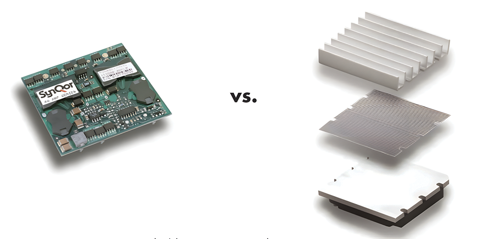


SynQor recently produced a white paper to demonstrate how its PowerQor family of synchronous rectifier-based DC-DC converters provide more usable output power without a heatsink than do conventional, Schottky diode-based converters with a heatsink.
The company’s approach was to firstly study how much heat-removal capacity was lost when the converters heatsink is removed. Next, they determined how much less heat is needed to be removed from its high-efficiency PowerQor converters compared to the standard low-efficiency conventional converters. Finally, power derating curves for both converters were compared to see how the PowerQor converters gain more from their high efficiency than they lose from not having a heatsink.
The study was focused on the standard half-brick size DC-DC converter (2,3 x 2,4-inch). In general, the best Schottky diode-based converters of this size can deliver 150 W or 30 A to their output. This is the rating of the device. However, the actual power that the converter can deliver is usually substantially less than this rating in a user’s worst case thermal environment.
What do we lose when we take the heatsink away?
The purpose of a heatsink is to increase the surface area that the cooling airflow contacts so that the thermal resistance to that air is reduced.
It is convenient to measure the effectiveness of a heatsink by comparing it to the situation where no heatsink is used. For instance, a conventional DC-DC converter that has a baseplate with no heatsink attached will have a certain thermal resistance, RCA(w/o heatsink), between that baseplate and the flowing air. If a heatsink is then attached to this baseplate, the new thermal resistance, RCA(heatsink), will be smaller than RCA(w/o heatsink) by some factor. This factor specifies the value of the heatsink.
Ideally, if the surface area of the heatsink’s fins were twice the area of the converter’s baseplate, then it would reduce the thermal resistance between the baseplate and the air by a factor of two. Such a one-to-one correspondence is not achieved for several reasons:
• First, there is a thermal resistance associated with getting the heat from the baseplate up into the heatsink’s fins. This additional resistance comes partly from the thermal pad (or thermal grease) that is placed between the baseplate and the heatsink to fill the gaps, and partly from the need for the heat to flow up through the narrow fins.
• Second, not all the cooling airflow makes its way into the spaces between the heatsink’s fins at the same flow rate that it crosses a flat baseplate.
Both these phenomena cause the heatsink to provide less heat-removal than would be expected from its increased surface area.
How much smaller is the heat dissipation in the SynQor converters?
Conventional converters use Schottky diodes to rectify the output of their transformers. The Schottky diodes dissipate most of the heat lost in these converters. SynQor’s PowerQor line of DC-DC converters use synchronous rectifiers to rectify the output of their transformers. The synchronous rectifiers in the PowerQor converters greatly reduce the heat dissipation that would otherwise occur in the Schottky diodes of a conventional converter.
Why we need to look at the power derating curves before we make comparisons?
We know the amount of heat-removal that is given up when the heatsink is eliminated, and how much the SynQor 30 A PowerQor converters reduce the amount of dissipated heat. It would seem that a simple comparison would tell us whether we gain more from the higher efficiency of a SynQor converter than we lose by getting rid of the heatsink. A true comparison is not so simple, however.
One reason is that the SynQor converter does not have a metal baseplate. Instead, it has an open-frame structure that displays several significant differences. First, it has a lower height than a conventional converter (0,4-inch vs. 0,5-inch without the heatsink) so that air will more readily pass over the SynQor converter instead of going around it. Second, its upper surface is irregular, which promotes a turbulent airflow that removes heat better than a linear airflow. Third, there is room for air to flow under the SynQor converter, which also increases the removal of heat.
A second reason that the comparison is not so simple is that a converter’s efficiency is a function of both its output power and its temperature. SynQor’s converters are designed to hold their high efficiency relatively constant throughout most of their power range, and this efficiency decreases only slightly as the converter gets hotter.
For these reasons, the best way to determine whether we gain more than we lose is to look directly at the power derating curves. Power derating curves show how much power a DC-DC converter can deliver as a function of the temperature and the flow rate of the ambient air. Each point on a power derating curve represents a combination of output power and environmental condition that causes the temperature of some component within the converter to reach a predetermined limit.
Manufacturers of conventional DC-DC converters specify that users should keep the baseplate of their converters below some maximum limit (typically 100°C). Hotter ambient air, slower airflow, and shorter heatsinks all translate into less power that the user can extract from the converter before the baseplate reaches this limit.
Since the SynQor converters do not have a baseplate, we look directly at our components to tell us when we should limit the output power of the converter. We have decided that our power MOSFETs, which are rated for 150°C operation, should not get hotter than 125°C. In addition, we have decided that our PCB, which is rated for 130°C, should not get hotter than 120°C (or 110°C near the isolation barrier). Choosing these values well below the components’ actual rated temperature limits allows significant built-in margins for the derating curves. You can therefore feel more comfortable using the SynQor converter at the limits of its derating curves.
Note that for conventional converters the specification sheets do not mention how hot the components within the converters get when you let their baseplates reach 100°C. We therefore do not know how much margin, if any, is designed into the power derating curves of these converters. If we assume the worst, we would probably like to add in some margin by not using these converters at the limits of their derating curves.
How do the power derating curves compare for 3,3 VOUT converters?
Except where specifically mentioned all the power derating curves presented in this document were derived by making measurements on the actual DC-DC converter. To do this a wind tunnel was set up in which the temperature and the flow rate of the air could be controlled. The converter was mounted on a PCB within this wind tunnel and thermal images of it through a window on the side of the tunnel were taken.
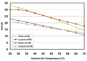
Figure 2 shows the power derating curves for two brands of 3,3 V output Schottky diode-based converters. For each brand there are a set of curves for the situation where a 0,5-inch high heatsink is attached to the converter and another set of curves for the situation where no heatsink is used. A similar set of curves could be shown for other brands, other output voltages, and other heatsink heights.
Some manufacturers provide the user with all the information they need to create these power derating curves for each of their converters, while others do not.
As can be seen from these curves, the actual power one can get from a half-brick size conventional converter is less than its ‘rating’. For instance, even with a 0,5-inch-high heatsink, you can only draw 22 A from the Lucent JW150 converter if the worst-case environment is 55°C and 200 LFM. If there is no room for a heatsink, only 15 A can be drawn.
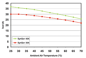
In comparison, figure 3 shows the power derating curves for the PowerQor 3,3 V 30 A and 40 A half-brick converters. Remember that these curves are for a converter that has no heatsink and no metal baseplate.
As can be seen, the high-efficiency SynQor 3,3 VOUT converters can deliver significantly more output current and power without a heatsink than the conventional 3,3 V converters can with a 0,5-inch heatsink. The SynQor converters deliver substantially more power if there is no room for a heatsink regardless of which converter is chosen.
Conclusions
The data presented in this paper shows that DC-DC converter technology has taken an evolutionary leap forward. By using synchronous rectification and an improved design, the SynQor converters can provide impressive gains in efficiency, especially at the lower output voltages. As a result, the PowerQor converters dissipate less than half the heat of conventional converters for the low output voltages of today’s logic circuits. This allows the converters to operate with no attached heatsink or baseplate, which reduces the height, weight, cost over a converter with a heatsink.
| Tel: | +27 12 667 5212 |
| Email: | [email protected] |
| www: | www.rfibersolutions.com |
| Articles: | More information and articles about RFiber Solutions |






© Technews Publishing (Pty) Ltd | All Rights Reserved
 printer friendly version