


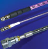
The environments in which microwave cable assemblies are being used today are becoming more challenging with exposure to such conditions as extreme temperatures, chemicals, abrasion and flexing. Additional challenges include the need for smaller, lighter packaging for cable systems that last longer and cost less.
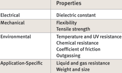
To ensure signal integrity and product reliability, it is essential to identify the electrical, mechanical, environmental and application-specific constraints that can affect the cable’s overall performance. These variables have a direct impact on the materials used for cable dielectric and jacketing, as well as the construction of the cable. Also, testing and data analysis are key to ensuring that the cable will, in fact, perform reliably in a specific environment.
Identifying constraints
Environmental influences are having more of an impact on microwave/RF cable assemblies. Electrical performance is probably the first and foremost consideration, and many factors can potentially compromise signal integrity, such as internal and external electromagnetic interference (EMI), voltage standing wave ratio (VSWR) and insertion loss.
Electrical performance is typically very reliable when no other environmental factors are involved; however, when mechanical, environmental or application-specific stress is added, maintaining reliable electrical performance can be more challenging.
Mechanical stress occurs when cables are exposed to various types of movement. Flexing creates kinetic energy in the cable, which can cause severe damage if not properly managed. One of the biggest causes of mechanical stress on a cable is when it is part of equipment handled by a person. An operator can kink, pinch or crush a cable by stepping on it or rolling over it.
Therefore, crush and tensile strength are essential in overcoming mechanical stress. Also, cables used with portable equipment can come into contact with sharp surfaces that cut them or expose them to abrasion. When the complexities of compensating for vibration or gravity are added, mechanical stress can significantly compromise stability and cause premature failure of a cable.
Environmental stress results from the physical area in which the cables are used
Extreme temperatures and pressures affect cable materials. Low temperatures make them brittle and high temperatures cause them to become very soft. Vacuum leaches oils and additives out of a cable, contaminating a clean-room manufacturing process, while hydrostatic pressure causes gas or liquids to permeate cable jackets.
Radiation can damage both dielectric and jacket materials depending on the type and dosage level. Friction resulting from cable movement can compromise cable jackets by causing particulation, while contaminants such as mud, chemicals or metal chips can damage the cable jacket. Environmental stress can significantly compromise dielectric and jacketing materials, so these issues must be taken into account when designing a cable assembly.
Application-specific stress results from constraints that are unique to the application in which the cable will be used. In aerospace applications, cables need to be the lightest and smallest possible size in order to minimise mass during take-off. If the cables are used by technicians or other personnel, safety issues such as flammability, voltage and halogen use are factors.
One of the added complexities of designing cable assemblies is that electrical, mechanical and environmental performance is interwoven. Each has a direct impact on the other; so the design must be thoroughly tested in the specific application.
Choosing the right materials
Ensuring high-quality signal stability means evaluating the dielectric and jacket materials for attributes that account for the harsh elements of the application. The dielectric materials used in signalling cables affect the signal integrity as well as robustness of the cable.
The material used in an outer jacket affects maximum voltage and resistance to abrasion. Jacket materials must survive most of the external factors (eg, temperature, friction, liquids and gases) to protect the conductors inside the cable.
The list of possible materials used in cable dielectric and jacketing is very long, and many of these have been developed for specific applications. Because each material has unique properties, some are more appropriate than others for use in microwave cables engineered for challenging environments.
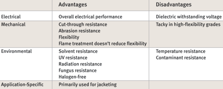
Silicone
Silicone is primarily used as a cable jacket and is very flexible even at low temperatures (Table 1). However, it cuts easily, and its sticky surface results in a high coefficient of friction, so it is not good for clean-room environments. Silicone’s tensile strength and tear resistance are low, therefore requiring it to be thicker compared to other jacket materials.

Some surface treatments are available to reduce the coefficient of friction, but these tend to wear off over time. Silicone has very good radiation resistance, but the grades of silicone used for cable jackets are known to outgas silicone oil in vacuum applications such as a thermal vacuum chamber. If weight is an issue, silicone is not the optimal choice.
If flexibility is important and weight is not a factor, silicone is a good choice.
However, it is more labour-intensive to gain access to the conductors, which results in higher costs for termination.
Polyurethane
Polyurethane is a good jacket material, but it is not used as a dielectric material because its dielectric withstanding voltage is low when compared to other materials, as shown in Table 2. Halogen-free grades are available. Mechanically, polyurethane is flexible, and it is very resistant to cut-through and abrasion.
Treatment for flame resistance does not reduce its flexibility; however, the more flexible grades tend to be sticky or tacky, which results in a higher coefficient of friction. Environmentally, polyurethane is resistant to solvents, UV rays, radiation and fungus. Polyurethane does not have a very broad temperature range; it becomes brittle around -40°C, and its upper temperature limit is around 100°C. Also, polyurethane cannot survive the chemicals used for cleaning.
Polyethylene
Polyethylene is most appropriate as a dielectric for conductors because polyethylene jackets tend to be stiff, which affects the flexibility of the cable – Table 3. Polyethylene has good dielectric constant properties when used in conjunction with foam.
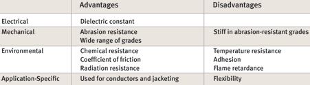
Mechanically, high molecular-weight polyethylene is abrasion-resistant and low-friction, but it is also stiff when compared to other materials. Like polyurethane, polyethylene’s temperature range is rather limited, and it is difficult to bond chemical boots to polyethylene cable jackets. Overall the mechanical properties of polyethylene are reduced by flame-retardant treatments.
Fluoropolymers
Fluoropolymers such as fluorinated ethylene propylene (FEP), perfluoroalkoxy (PFA) and polytetrafluoroethylene (PTFE) are excellent jacket materials, particularly in applications when the cost of system failure is high (Table 4).
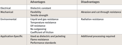
The dielectric withstanding voltage of fluoropolymers is among the highest of any dielectric material. They can withstand extreme temperatures, but each material has its own range: FEP can handle temperatures ranging from -250°C to 150°C, while PFA ranges from -250°C to 200°C. PTFE is suitable for temperatures from cryogenic to 260°C without losing flexibility.
Fluoropolymers can also withstand exposure to chemicals, acids, and aggressive solvents, and they are naturally non-flammable. PTFE and its co-polymers also have the benefit of low outgassing, which is critical for ultra-high vacuum (UHV) environments. Most fluoropolymers are flexible; but like temperature resistance, flexibility varies depending on the specific material. PFA is the stiffest, followed by FEP and PTFE, while engineered PTFE is the most flexible.
Anything that is added to a cable’s dielectric, jacket, conductors or shield wires will outgas in a vacuum. When materials outgas, particulate matter condenses on cooler surfaces, which are typically the work surfaces in the application area. In a satellite, optics can become fogged by silicone oil or other processing lubricants that outgas from a cable. PTFE is chemically inert and does not contain any process additives, oils, lubricants or plasticisers, which makes it the best material for vacuum environments.
Engineered fluoropolymers
One of the few negatives of fluoropolymers is that they are not very resistant to abrasion and cut-through. Certain fluoropolymers can be engineered to enhance their physical, chemical and electromagnetic attributes, which improves a cable’s ability to withstand the specific challenges of a microwave application.
Ethylene tetrafluoroethylene (ETFE) can be irradiated to improve its mechanical properties and chemical resistance; however, irradiation increases stiffness, so there is a significant decrease in flexibility. PTFE is naturally thermally resistant and chemically inert, so its temperature and chemical properties are not altered when engineered to enhance electrical or mechanical attributes.
Specialised technologies have been developed to engineer PTFE so that it can withstand a wide variety of environmental and mechanical challenges, as seen in Table 5. The dielectric materials used to insulate conductors can significantly affect insertion loss, cable size and flexibility. The lower the dielectric loss, the less insertion loss the cable exhibits.
Typical fluoropolymers have a dielectric loss of 2,1. To reduce cable size, PTFE can be engineered to have a dielectric constant of 1,3. At the same time, its dielectric withstanding voltage can be increased by a factor of 2,5 while achieving a very low loss tangent of 0,00015 at 10 GHz compared to PTFE’s standard construction.
With these attributes, a conductor insulated with a 50 micron layer of engineered PTFE can be rated for use at 1000 V. Another version of engineered PTFE can be made semiconductive and used to increase the effectiveness of a cable’s shield. For issues of abrasion or cut-through resistance, PTFE has been engineered to attain a tensile strength that is 50 times greater than standard PTFE and to withstand temperatures from cryogenic to 300°C.
Verifying the design
Some industries have defined safety, environmental and performance related standards for cables, but many rugged applications that use microwave cables require going beyond the standards. In these kinds of situations, the manufacturer may need to develop additional tests that evaluate the cable’s electrical performance while simulating mechanical and environmental stress similar to that in the application.
It is essential to monitor electrical performance and signal integrity throughout all of the testing, and the specific type of testing that is needed depends on the environmental constraints of the application.
Phased-array applications require close phase tracking of multiple assemblies of the same type and length to minimise residual systemic error. These errors eventually affect system range, clutter and jamming resistance, and overall accuracy. Problems with phase tracking most often occur either because of poor materials and process control during cable assembly manufacturing or because assemblies from different manufacturers’ components were combined. So phase tracking and stability should be thoroughly tested in the environment in which the cables will be used.
Mechanical testing verifies electrical performance while the cable is operating in environmental conditions such as crushing, abrasion, potential cut-through, tight bending, continuous flexing, shock and vibration. Using microwave/RF cables generally means that the application requires excellent phase stability, which can be affected with bending and flexure, whether during installation, routine maintenance or actual use.
Random flexing is a frequent issue with a handheld test instrument because the cable assembly is often wrapped around the instrument to carry it. The impact of these movements on system performance must be evaluated during system design. In the lab environment, a technician could roll over the cable with a chair, which means that crush strength is also an issue.
Random flexing motion is very difficult to model in a test lab, but the worst-case scenario can be modelled using a tic-toc test with repeated bending of 180° or more. Then a pull test can simulate a cable being used as a tether. During these tests, insertion loss and VSWR should be evaluated.
The cable’s electrical performance should also be measured while simulating the environmental conditions in which it will operate – conditions such as temperature, altitude and pressure extremes; vibration and acceleration; exposure to liquids or gas; or humidity. It is important to monitor impedance during altitude change, mechanical shock and vibration tests. Vibration and shock can cause mechanical and electrical failure due to metal fatigue or cracking of solder joints.
Temperature changes have a direct impact on phase length. As the temperature approaches an extreme, the electrical length will change; if it does not change at the same rate as the temperature when returning to normal (a state known as hysteresis), it is very difficult to apply error-correction techniques to the signal. Adding a clamp force during a temperature cycling test allows monitoring of the cable’s dielectric withstanding voltage to see how the jacket and conductor change.
After the cable is put through substantive mechanical and environmental tests, the manufacturer should again verify that the electrical performance, dielectric and jacket materials remain stable within the requirements of the application.
For products that will be used in demanding environments, the consequences of cable failure are usually high. Therefore it is essential to ensure the electrical and mechanical integrity of the cable for the life of the application. To do this means understanding the factors that can compromise cable performance; selecting the right materials to address these factors; and verifying the cable’s reliability through electrical, mechanical and environmental testing.
| Tel: | +27 11 918 0011 |
| Email: | [email protected] |
| www: | www.cwservices.co.za |
| Articles: | More information and articles about Connector & Wire Services |


© Technews Publishing (Pty) Ltd | All Rights Reserved
 printer friendly version