

Test & Measurement


iOLM technology eases FTTx/PON network testing

23 January 2013 Test & Measurement

Of the current test methods for testing FTTx (Fibre to the ‘x’, with x being a placeholder for various end-points) and PON (passive optical network) installations, OLTS, using an optical loss test set (optical power meter and light source) to characterise a link is easy; however it has one major limitation: it cannot locate the problems on the link. Furthermore, an OLTS requires two units and two technicians, thus increasing OPEX.
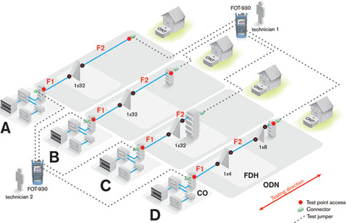
Figure 1. End-to-end test with a pair of OLTS units. This method may be fast, but will not locate the problem on the link.

The most popular test method during construction and in certifying FTTX/PON installations is an OTDR (optical time domain reflectometer). A well trained and skilled optical technician can identify and locate problems on a link, using multiple acquisitions with different OTDR test settings and after various manual OTDR trace comparisons.
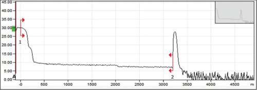
Figure 2. Incomplete OTDR test results on a 1x32 PON due to improper testing parameters set by a technician who is lacking OTDR testing experience.

The shift from copper to fibre and the explosion of fibre deployments has created a shortage of skilled and experienced technicians. Combine this with budget constraints, lack of credible training facilities, practical experience and the result is an increased risk of improper testing, misdiagnoses, unusable OTDR results and repeat repairs/truck rolls.
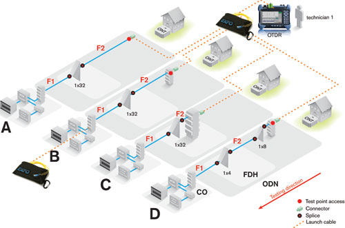
Figure 3. Portable test setup with launch and receive fibres for a PON-line certification with a 1x32 splitter.

The complexity of a PON/FTTx network requires skilled optical technicians to set different acquisition parameters on the OTDR to get the required information. Single OTDR measurement and auto test settings on today’s OTDRs are incapable of fully characterising this type of network.

To overcome this limitation, skilled technicians perform multiple additional acquisitions on the OTDR with other parameters to fully characterise the link.
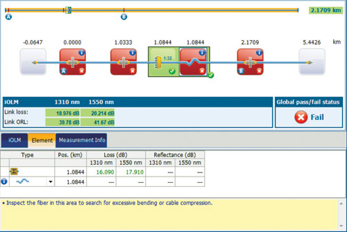
Figure 4. Example of test results. All the information, including diagnostics, is provided in a single view.

Portable applications

EXFO’s new test solution is an ‘intelligent’ OTDR. Essentially it is a software application that runs on the test unit that is able to set and take multiple and variable acquisitions, then analyse the information to generate a detailed linear diagram about every element on the link, in a single-button operation, providing maximum simplicity for expert-level link characterisation.

This new test method makes every technician a fibre-optics expert, whether they are testing in the field or from the central office. Plus, it does not require the parameter settings used in traditional OTDR testing, which means no distance, pulse width or averaging time setting with detection threshold setting required.

iOLM (intelligent Optical Link Mapper) technology stems from the need to create optimal testing technology for PON networks, as this is the most challenging network to test because of its short link lengths and many closely spaced elements, such as splices, connectors and splitters.

As shown in Table 1, the maximum IL difference between iOLM and the reference method (PM/LS) is 0,64 dB, which compares favourably to the OLTS method. Based on the PM/LS and the OLTS results, an experienced technician could have suspected a macrobend on the line because the difference in loss is more than 1 dB between 1310 and 1550 nm.
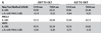
Table 1. IL test results from the different methods.

However, he would have no clue as to the location of the macrobend. He could therefore use an OTDR and a different combination of pulse widths to find the macrobend himself. With iOLM any technician will be able to clearly see that there is a macrobend immediately after the splitter (see Figure 5 showing a test conducted from ONT to OLT).

Figure 5. Image showing the position of a macrobend once analysed by a portable OTDR with multi-pulse acquisition and analysis capabilities.

The test method is a one-end, single-unit testing method with the ability to provide clear diagnostics and discovered elements in a single view.

Comparing ORL measurements (Table 2), the maximum difference between the ORL meter and iOLM is 0,84 dB, which is small enough to locate any ORL problem.
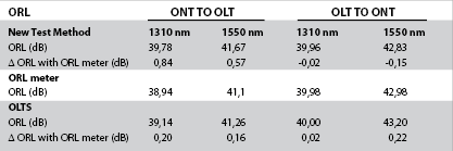
Table 2. Table showing the different ORL test results.

So what is causing an ORL issue on the line?

This is caused by connector reflectance, but according to the ORL results, we are below the 32 dB threshold. Now, if we look at the results in Figure 6, we can see that there is one highly reflective connector that needs to be fixed (exceeds the -55 dB threshold).

Figure 5. Image showing the position of a macrobend once analysed by a portable OTDR with multi-pulse acquisition and analysis capabilities.

This is what we are looking for when testing with an ORL meter (or OLTS) in both directions. We want to know the direction of the high ORL because that is where the high reflective connector is. Obviously, we would have missed it with the ORL meter or the OLTS, providing a clear advantage for the iOLM.

For more information contact Chris Nel, Lambda Test Equipment, +27 (0)12 349 1341, [email protected], www.lambdatest.co.za


Credit(s)


Share this article:
Share via emailShare via LinkedInPrint this page

Further reading:

AI Experts provide product-specific intelligence
Measuretest Test & Measurement
VIAVI Solutions has announced AI Experts, the first addition to its NITRO AI portfolio of AI-driven capabilities with each Expert providing product-specific intelligence.

Read more...
Rugged spectrum analyser
Vepac Electronics Test & Measurement
The HAROGIC PXR Series is designed for maximum durability and performance in the most demanding environments.

Read more...
Setting a new benchmark for high-power DC load testing
Conical Technologies Test & Measurement Power Electronics / Power Management
The new ITECH IT8900G/L high-speed, high-power DC electronic load offers a powerful combination of speed, scalability, precision and high-power density.

Read more...
Locate underground cable faults faster with the Fluke AF2082 A-Frame
Comtest Editor's Choice Test & Measurement
Underground cable faults can lead to costly downtime, service disruptions, and extensive excavation if the fault location is uncertain. The AF2082 simplifies this process by guiding operators directly to the fault point.

Read more...
Precision power for electronics testing
Vepac Electronics Test & Measurement
The PeakTech 6168 switching power supply is a versatile and reliable solution designed for professional applications in laboratories, development environments, service centres, and training facilities.

Read more...
12-bit 1-wire temperature sensing
RS South Africa Test & Measurement
The DS18B20 digital thermometer from Analog Devices provides 9-bit to 12-bit Celsius temperature measurements in the range -55°C to 125°C.

Read more...
Ultra-fast wideband RF insight
Vepac Electronics Test & Measurement
The Harogix PXE-200 is a high-performance real-time spectrum analyser designed for demanding RF environments up to 20 GHz.

Read more...
Field calibration made easy
Instrotech Test & Measurement
Built around modern component technology, an intuitive interface, and a rugged IP54-rated housing, Instrotech’s Calog series is engineered for the demands of real industrial field calibration work.

Read more...
Rugged two-pole voltage tester
Vepac Electronics Test & Measurement
A key advantage of the PeakTech 1094 is its battery-free operation, ensuring the tester is always ready for use whenever required by professional electricians or maintenance personnel.

Read more...
Rapid IoT prototyping simplified
Future Electronics Test & Measurement
The STEVAL-MKBOXPRO from STMicroelectronics is a compact, ready-to-use wireless development kit designed to accelerate the creation of intelligent IoT and wearable applications.

Read more...


While every effort has been made to ensure the accuracy of the information contained herein, the publisher and its agents cannot be held responsible for any errors contained, or any loss incurred as a result. Articles published do not necessarily reflect the views of the publishers. The editor reserves the right to alter or cut copy. Articles submitted are deemed to have been cleared for publication. Advertisements and company contact details are published as provided by the advertiser. Technews Publishing (Pty) Ltd cannot be held responsible for the accuracy or veracity of supplied material.


© Technews Publishing (Pty) Ltd | All Rights Reserved