


Today’s integrated circuits (ICs) are designed with ever-smaller geometries and higher processing speeds. These design features cause semiconductors to become increasingly vulnerable to electrostatic discharge (ESD) damage.
ESD can be triggered by human touch, machine handling, testing by automated testers, or by pre-charge events such as friction produced by the handlers. ESD poses a serious threat to every IC design facility and fabrication process house.
ESD-related failures are estimated to cost millions of dollars in lost revenue for IC manufacturers every year.
In battling ESD, factories are equipped with conductive flooring materials to conduct the electric charges from the work area. Operators handling ICs are required to wear special coats with conductive filaments, and/or heel-straps. At the work bench, operators are required to wear wrist straps to ensure that they are grounded.
However, based on investigations by ESD experts, less than 0,10% of all documented damage actually comes from ungrounded personnel touching ESD-sensitive products. In other words, 99,9% of ESD damage is attributed to charging/discharging events that occur in production equipment and processes. Consequently, maintaining ground integrity for equipment plays a vital role in the reduction of ESD.
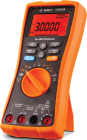
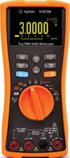
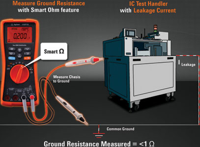
This article shows how to obtain an accurate ground resistance measurement in the presence of offset voltage, using Agilent Technologies’ U1272A/U173A handheld digital multimeters with Smart Ohm technology.
Ground resistance
In the manufacturing industry, electrical circuits are connected to ground for several reasons. The equipment’s exposed metal parts are connected to ground to prevent contact with a dangerously high voltage if the electrical insulation fails. Grounding also serves to drain off static electricity charges on the metal part before a spark-over potential is reached.
For a brand new installation, grounding connections on the tester may be good; but after some time, the wires may bend, stretch and break. Ground resistance will then tend to increase. If proper grounding checks are not performed consistently, semiconductors may be damaged due to ESD.
So, what is a good ground resistance value? Ideally, it should be zero ohms. In the IC testing environment, any reading below 1 ohm is considered good.
Measuring resistance
When measuring ground resistance, the residual voltage induced by ground current should be taken into consideration. Even a small offset voltage of 7 mV can cause deviation in measurements.
With a regular handheld multimeter, one would have to perform multiple voltage measurements and use an external current excitation source to get the exact measurement result.
Now, the Agilent U1272A/U1273A handheld multimeters with the new Smart Ohm feature simplify the whole process. A circuit designer can also measure leakage current using the function, instead of having to use a high-precision multimeter with 1 nA, 0,1 nA, or a precision shunt.
Smart Ohm is an offset compensation function that removes the effect of any voltage in the circuit being measured. Once the Smart Ohm function is enabled, the U1272A/U1273A performs two resistance measurements, one with the current source turned on, and one with the current source turned off. The difference is then used to compute ground resistance.
The result is displayed on the screen while the amount of leakage current or offset voltage is shown on the handheld’s secondary display.
How does Smart Ohm work?
In every resistance measurement, the digital multimeter supplies a test current of 1 mA and then measures the voltage drop across the unit under test. The measured voltage drop is then used in the calculation for resistance. However, this technique is not able to generate an accurate resistance measurement in the presence of residual voltage; the offset has to be removed first.
Step 1. The offset compensation technique makes a voltage measurement with 1 mA supply to the device under test – see Figure 1. This measurement measures the residual voltage, plus the voltage drop across RGND (ground resistance due to the 1 mA test current).
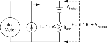
From this circuit:
E = VResidual + (I * R)
= 7,0 mV + (1 mA * RGND)
= 7,2 mV (measured)
Step 2. During the second measurement, the current source is switched off (Figure 2) to measure the residual voltage due to the ground current.

Now:
VResidual = 7 mV (measured)
VDifferent = E – VResidual
= 7,2 mV – 7,0 mV
= 0,2 mV
RGND = VDifferent/1 mA test current
= 0,2 mV / 1 mA
= 0,2 Ω.
Only using Step 1 for resistance measurement produces a resistance measurement with offset error:
RGND Error = E / 1 mA test current
= 7,2 mV / 1 mA
= 7,2 Ω
Ratio = RGND Error / RGND
= 7,2 Ω / 0,2 Ω
= 36
Sometimes the measurement value can be up to 100 times higher than the original value.
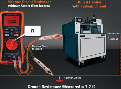
Figure 3 illustrates how ground resistance measurement is simplified with the Agilent U1272A/U1273A.
Conclusion
Proper grounding is the most fundamental element of ESD management in manufacturing and service. A broken ground connection may result in personnel exposure to dangerous voltage, equipment lock-up or malfunction, and damage to sensitive components.
Only continuous ground monitoring can assure proper grounding at all times. The Agilent U1272A/U1273A with their Smart Ohm function are ideal tools for maintenance technicians or engineers to ensure their equipment is properly grounded.
| Tel: | +27 12 678 9200 |
| Email: | [email protected] |
| www: | www.concilium.co.za |
| Articles: | More information and articles about Concilium Technologies |


© Technews Publishing (Pty) Ltd | All Rights Reserved
 printer friendly version