


Despite advances in modulation formats and equipment management systems offered with monitoring tools, faults, issues, delays and errors still occur all too frequently in wavelength-division multiplexing (WDM) networks.
When this happens, the optical spectrum analyser (OSA) is a tool of choice for identifying the issue, and helping to fix it.
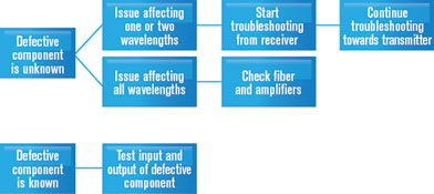
However, as networks become more and more complex (tighter channel spacing, mesh and ROADM-based, polarisation-multiplexed signals, etc.) the number of potential causes for failure increases, making it extremely difficult to find the issue for a given failure. Most providers and vendors have developed their own best practices involving use of an OSA to locate the issue. Figure 1 shows a typical best-practice procedure.
Although this procedure works well, it is case-by-case dependent, and involves a certain level of knowledge of the system, some trial and error, and ultimately, a certain number of truck rolls, time and unavoidable extra OPEX.
WDM Investigator
EXFO’s next-generation optical spectrum analyser and software bring more than mere pass/fail values, and are designed to ensure efficient turn-up and maintenance of any network, by giving information on a per-wavelength basis on the link. In addition, the system tells users what could be causing high optical signal-to-noise ratio (OSNR) measurement when it occurs, since even good OSNR systems can generate unacceptable bit error rates (BER).
BER tests are long and as such, when they fail, there are huge cost implications. New systems can create noise that is not taken into account in traditional OSNR measurement, ie, power, less amplified spontaneous emission (ASE) noise. With EXFO’s WDM Investigator, users can carry out large-scale network prevention and maintenance before the latent issue becomes a problem.
Figure 2 shows a screen capture of WDM Investigator’s user interface. To perform WDM Investigator impairment testing, an i-in-band acquisition is required to ensure that 500 polarisation condition scans are carried out.
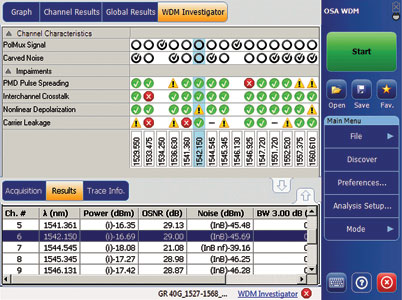
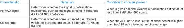
The WDM Investigator provides two types of feedback: link information and impairment detection. Table 1 outlines the details available in the link information. Three levels of information are given for link information diagnostics: no information available; detected as present; and clearly not present.
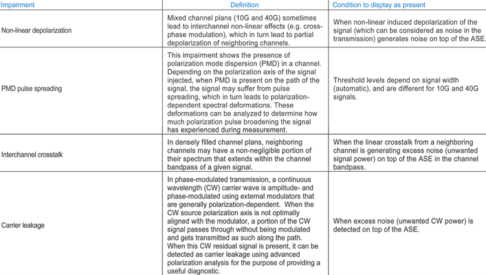
Impairment detection checks for the presence of several types of impairments and gives an assessment of their severity. This information is available for polarised signals only. When a signal is detected as pol-MUX, no diagnostic is provided. Table 2 describes all the impairments found in the WDM Investigator.
Four levels of information are provided for impairment diagnostics: no information available; good – no visible effect (below threshold); warning – some effect (threshold up to a level x); and risk – clear effect (above level x).
Most of these impairments frequently lead to an overestimation of the ASE level for polarisation-based in-band OSNR techniques. As such, correct identification of these impairments helps improve the ASE-level determination of polarisation-based techniques.
Conclusion
Standard OSAs can only determine whether a given channel was experiencing noise. Now, with the EXFO WDM Investigator software, an OSA can identify several types of impairments on a per-channel basis (PMD pulse spreading, non-linear depolarisation, interchannel crosstalk, carrier leakage, etc.), which provides greater visibility within a WDM network.
In addition, the WDM Investigator provides useful information on the link characteristics, such as the presence of polarisation-multiplexed signals or the presence of carved noise due to filters or ROADMs. The impairment identification and link characteristics both significantly help pinpoint the exact failure affecting a channel, thereby drastically reducing turn-up time and even helping to prevent future failures.
Link information and impairment detection terms
Pol-MUX signal
Pol-MUX (polarisation-multiplexed) signals are playing an increasing role in optical communications. Pol-MUX channels are often added onto existing networks, in which case system architects carefully ensure that the channel plan and link characteristics allow for its introduction.
Identification of pol-MUX channels and their relative positions on the channel plan may be useful when troubleshooting issues specific to pol-MUX, eg, non-linear degradations. Pol-MUX channel identification is also useful for confirming that channel routing is correct, ie, that a channel that is expected to be pol-MUX is indeed pol-MUX.
Also, since most in-band OSNR measurement techniques (all commercially available) rely on polarisation properties of the signal, a pol-MUX confirmation indicates that the OSNR, when provided by ‘standard’ polarisation-based techniques, will most likely not be accurate.
Carved noise
A check mark for carved noise may be useful in determining whether some of the channels have gone through a different optical route than their neighbours. Detecting the presence of carved noise also indicates that the IEC method for OSNR measurement is not appropriate for this channel because of the presence of filters/ROADMs in the signal path. If the signal is not pol-MUX, then the in-band OSNR method is ideal.
Non-linear induced depolarisation
Non-linear effects can lead to the partial depolarisation of a modulated signal in such a way that the depolarisation part is like optical power removed from the signal and added to the noise. Non-linear effects can generate bit errors, reducing the margin to the FEC limit if they become dominant.
When designing their links, system architects try to minimise these effects by managing the launched powers (distance between amplifiers and types of amplifiers), the channels spacing and relative positions (10G vs. 40G), and the dispersion map (also affecting amplifier deployment).
PMD pulse spreading
This impairment indicates the presence of PMD-induced pulse broadening for that channel, a phenomenon that depends on the fibre properties (and the properties of certain components in the path) as well as environmental stresses. Large PMD pulse spreading may explain why increased BER no longer correlates with the OSNR (ASE) of the system.
Interchannel crosstalk
When interchannel linear crosstalk is present in a given channel, the noise power within that channel is increased and, depending on the polarisation relation between the neighbouring channel and the channel of interest, the resulting beat noise may lead to increased BER, which would again no longer correlate with the OSNR (ASE) of the system.
Carrier leakage
Normally, transmitters are tested during manufacture to ensure a minimal carrier extinction ratio (eg, 20 dB), but in practice, some transmitters found in the field may exhibit insufficient extinction.
For more information contact Chris Nel, Lambda Test Equipment, +27 (0)12 349 1341, [email protected], www.lambdatest.co.za
| Tel: | +27 12 349 1341 |
| Email: | [email protected], [email protected] |
| www: | www.lambdatest.co.za |
| Articles: | More information and articles about Lambda Test |


© Technews Publishing (Pty) Ltd | All Rights Reserved
 printer friendly version