


When using a digital multimeter (DMM) for AC voltage measurements, it is important to know if the meter is providing peak value, average value, root-mean-square (RMS) value, or something else. If the answer is ‘something else,’ trouble may ensue, and the trouble usually happens with RMS measurements.
This article investigates the different techniques DMMs use to measure RMS values, how the signal affects the quality of measurements, and how to avoid common measurement mistakes.
Measuring RMS
Measuring RMS values is more complicated than it appears at first glance. If it is complicated, why do we bother? Because true RMS is the only AC voltage reading that does not depend on the shape of the signal. It is often the most useful measurement for real-world wavefoRMS.
Often, RMS is described as a measure of equivalent heating value, with a relationship to the amount of power dissipated by a resistive load driven by the equivalent DC value. For example, a 1 Vpk sine wave will deliver the same power to a resistive load as a 0,707 V d.c. signal. A reliable RMS reading on a signal will give a better idea of the effect the signal will have in a circuit.
Figure 1 shows four common voltage parameters. Peak voltage (Vpk) and peak-to-peak voltage (Vpk-pk) are simple. Vavg is the average of all the instantaneous values in one complete cycle of the waveform. How VRMS is calculated will be described shortly.
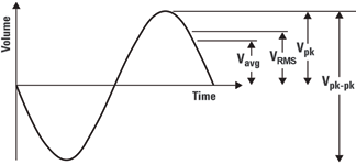
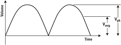
For sine waves, the negative half of the waveform cancels out the positive half and averages to zero over one cycle. This type of average would not provide much insight into the signal’s effective amplitude, so most meters compute Vavg based on the absolute value of the waveform. For a sine wave, this works out to Vpk x 0,637 (Figure 2).
VRMS can be derived by squaring every point in the waveform, finding the average (mean) value of the squares, then finding the square root of the average. With pure sine waves, a couple of shortcuts can be taken by just multiplying Vpk x 0,707 or Vavg x 1,11. Inexpensive peak-responding or average-responding meters rely on these scaling factors.
These scaling factors apply only to pure sine waves. For every other type of signal, using this approach produces misleading answers. Using a meter that is not really designed for the task can easily result in significant error – as high as 40% or more – depending on the meter and the signal.
The ratio of Vpk to VRMS – known as the crest factor – is important to measurement accuracy. The crest factor is a measure of how high the waveform peaks, relative to its RMS value. The higher the crest factor, the more difficult it is to make an accurate AC measurement.
Two measurement challenges are associated with high crest factors. The first involves input range, and can be understood by considering a pulse train with a very low duty cycle but a relatively high peak amplitude. Signals like this force the meter to simultaneously measure a high peak value and a much lower RMS value, possibly creating overload problems on the high end and resolution problems on the low end.
The second challenge is the amount of higher-frequency energy in the signal. In general, high crest factors indicate more harmonics, which can cause trouble for all meters. Peak- and average-responding meters that are trying to measure RMS have a particularly hard time.
Tips for making better RMS measurements
Given the importance – and difficulty – of measuring RMS, what is the best way to proceed with day-to-day measurement tasks? The following tips will help to achieve better results.
Tip 1: Understand how the DMM measures RMS
When it comes to measuring RMS values, multimeters are not created equal. A general understanding of the technology a multimeter uses to measure RMS will help in deciding if it meets one’s needs. The following is a summary of the operational advantages and disadvantages of four common multimeter technologies. The first three operate by converting AC to DC, while the last one digitises the analog input signal and then computes RMS.
Thermal AC-to-DC converters
This older technology for RMS measurements uses the equivalent-heating-value approach. The AC signal heats a thermocouple, then the DC section of the meter reads the thermocouple output. Advantages include wide bandwidth and the ability to handle very high crest factors, meaning this approach can deliver true RMS for a wide variety of real-world signals.
The disadvantages of the thermal approach are cost and lack of flexibility in trading off measurement speed with low-frequency accuracy. For these reasons, the technique is not used in the latest-generation DMMs.
When measurement of high-bandwidth and high-crest-factor signals with great accuracy is required, seeking out one of these thermal models may prove worthwhile. If high accuracy is important, multimeters that use the digital sampling method should be investigated.
Peak and averaging AC-to-DC converters
Inexpensive meters, particularly inexpensive handheld meters, usually derive RMS levels from either peak or average values. They deliver true RMS only for pure, undistorted sine waves. If true RMS measurements are required on real-world signals, these meters are not a viable option.
Analog AC-to-DC converters
Many mid-range DMMs use a chain of analog circuits to compute the square, then the mean, then the square root of the mean to deliver true RMS for nearly all signal types.
Digital sampling
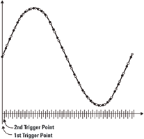
This last method uses sampling techniques similar to those in digital oscilloscopes to create a set of data points that are sent through an RMS algorithm. Synchronous sampling uses multiple passes to capture a signal as shown in Figure 3. Each subsequent pass is delayed by a small amount, and with enough passes, the signal can be digitised with very high resolution.
This technique has several advantages: true RMS on a wide range of signals, high accuracy, and the capability to create very fast, effective sampling rates and wider bandwidths, even with fairly slow analog-to-digital converters. This method, however, only works with repetitive signals.
If accurate RMS measurements are important and there is a likelihood of running into pulse trains and other complicated signals, a true RMS meter is the only solution. On the other hand, money can be saved with a peak- or average-responding meter.
Visit www.dataweek.co.za to read the rest of this article which explains how signal types affect measurement quality, and offers advice on how to avoid common traps.
| Tel: | +27 12 678 9200 |
| Email: | [email protected] |
| www: | www.concilium.co.za |
| Articles: | More information and articles about Concilium Technologies |


© Technews Publishing (Pty) Ltd | All Rights Reserved
 printer friendly version