


Cables may flex intentionally as part of a pre-programmed robotic move, or unintentionally due to operationally- or environmentally-induced vibration.
The most flexible test systems are backed by a large library of test boards that, for robotics applications, includes compatibility with, for example, nano- and micro-D connectors.
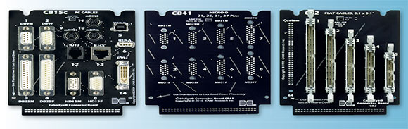
For optimal flexibility and usability, these boards are mounted with ‘families’ of connectors or connector slots (Figure 1). This is an especially agile and economical methodology, much appreciated by contract manufacturers and other companies where fast reconfigurability is necessary.
Such flexible cable and harness test systems may be used for all robotic applications, whether industrial, or service (e.g. personal, military, medical, logistic).
Pre-installation
Faults such as bad crimps, broken wires and cold solder joints will result in intermittent connections. The issue is whether test equipment is sufficiently sensitive to detect them, and whether the test is applied at the earliest possible point in the value-added stream – the earlier the testing, the less the impact of any detected error.
Those who buy connectorised cables for robotic applications will want to ensure their suppliers are shipping cables that have passed intermittence testing under fast cycle times. In this context, a full cycle comprises a complete sweep through all test points.
Testing for intermittent faults
The intermittence test is properly performed when the sample rate is high enough to statistically capture enough random events to raise the confidence level in the test result to an acceptably high degree. Companies running stringent quality programmes (such as Six Sigma) will be looking for the fastest cycle time possible. They need testers that deliver diagnostic information above a simple pass/fail, so they can provide quantitative and qualitative data to their process-improvement feedback loop.
Note that although the intermittence test mode is often referred to as the ‘continuous test’, the test signal itself is always pulsed in order to sweep through the full set of test points. In this context, ‘continuous’ simply means that the test is continuously sweeping through these test points.
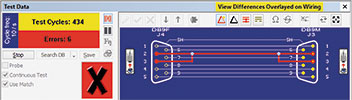
Testers are available that will sample 128 test points with 100 ms/cycle time using tester default settings, and as fast as 11 ms/cycle by reducing both dwell time (to zero) and the number of test points. Even faster speeds can be achieved by adjusting other parameters. These same testers include a dynamic GUI for identifying the type and location of the intermittent error (Figure 2), and can output ISO 9000-quality printed reports that include the same graphics.
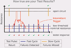
The probability of synchronising a pulsed test signal with the instant of an error increases as the cycle speed is increased. Figure 3 illustrates how a tester may deliver a false ‘pass’ if its sample rate cannot be set high enough to ‘capture’ the moment of error. In Figure 2, it can be seen that in 434 attempts (i.e. 434 full test cycles), six errors were captured at 100 ms/cycle while the cable under test was being flexed. If the sample speed had been set any slower, there would have been a high likelihood that this cable would have falsely passed the intermittence test.
Care must be taken when setting test parameters to avoid such false positives. Christopher E. Strangio, President of CAMI Research, notes that not all intermittence tests are equal, adding that, “We have seen a side-by-side test where under default settings CableEye easily indicates intermittent errors in a fixture that has been ‘passed’ by another brand of tester.“
To achieve the necessary sample rates, resistance measurements are not part of the intermittence test, and only opens and shorts are reported. However, tests additional to the intermittence test can be performed with cable and wire harness test systems, and some testers include separate resistance testing.
Ideally, an intermittent fault tester will permit testing at two thresholds in order to accommodate cables that have integrated resistive components. These types of cables may be tested in two stages. At the lower threshold, any line containing an integrated resistive component will deliver an ‘open’ error. Testing again at a threshold set above the known resistance of the integrated component is necessary to isolate whether or not there is a true open fault on that line.
Post-installation
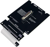
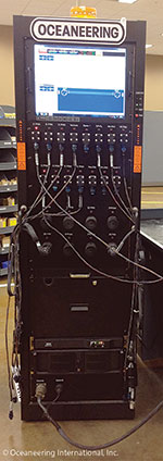
Cable diagnostics on failed, integrated robotic systems can be approached in several ways. If removal of each cable in turn for testing is not feasible, testing may be performed in situ using ‘full’ or ‘loop’ test protocols. For mobility, the tester itself may be on a mobile cart, even rack-mounted with other diagnostic equipment, and operated with a touch screen laptop (Figure 4):
In situ full test
For this type of testing, each end of the cable is disconnected and adaptors attached between each end of the cable and the tester. The intermittence test is executed while the robot performs the motion that flexes the cable.
In situ loop test
This is a two-step test that is often used when cables are very long, but may be applied to short cables in instances where the cable can neither be uninstalled nor is there room for fixtures at the ‘far’ end.
In step 1, with both ends disconnected, a shorts test is performed at one end. Continuity testing is carried out in step 2 after applying jumpers to pairs of pins at the ‘far’ end. At each step, after learning the cable setup an intermittence test will be carried out while the robot is performing the motion that flexes the cable. Using a macro feature that comes with the tester, the entire loop test sequence can be readily automated, simplifying the diagnostic test for the operator.
For mission-critical robots in particular, QC will want to create a maintenance schedule that includes testing for intermittent errors.
According to Strangio, cable and harness testers from CAMI’s LV (M2U/M3U) and HV (HVX/HVX-21) CableEye product lines all include an intermittence test option that can perform 54TP intermittent testing at 11 ms/cycle over any duration. Testing over extended durations is important for electrical life-testing of cables that undergo motion.
Conclusion
Cables in motion experience fatigue, causing complete or intermittent failures whether or not that motion is constant. Cable and harness test systems can easily identify and pinpoint the source of even the most elusive intermittent failure. Beyond continuity and resistance tests, diagnostic considerations for cables in motion are:
• Test for intermittent faults.
• Test early in the workflow – ideally at your supplier’s site.
• Use a fast enough intermittence test cycle to provide statistically significant sampling.
• Mission-critical robots require a post-installation maintenance schedule that tests for intermittent errors.
For more information contact Chris Viveiros, Otto Wireless Solutions, +27 (0)11 791 1033, [email protected], www.otto.co.za
| Tel: | +27 11 791 1033 |
| Email: | [email protected] |
| www: | www.otto.co.za |
| Articles: | More information and articles about Otto Wireless Solutions |


© Technews Publishing (Pty) Ltd | All Rights Reserved
 printer friendly version