


For production of printed circuit boards in a modern serial production, forced convection reflow ovens are used almost exclusively. However, considerable differences can be noticed regarding the process temperatures which are required to warm up a PCB to a required reflow temperature. This is a very important issue with regards to lead-free solder pastes which are intended to be introduced before the year 2004 at the latest in the European Community. Lead-free solder paste has a melting point of approx. 220°C and the board temperatures in the peak zone must be approx. 40°C higher than today in order to guarantee a safe soldering process. A large number of reflow soldering lines in today's production would then be operated at process temperatures above 300°C and are therefore not suitable for handling lead-free pastes.
Process gas flow in a forced convection reflow soldering system
In forced convection reflow soldering systems the process gas (ambient air or nitrogen as an inert atmosphere) is heated in separate heating zones and circulated by means of fans. The hot gases flow to the cold assembly, to which the heat is transferred. After this, the cooled and therefore used gas is drawn off, led back to a heating element where it is heated again to the set temperature and then is blown back to the assembly. Special attention is required for the air flow system/nozzles system. They should distribute a large circulating air volume evenly to the board and at the same time the blowing off of smaller components has to be avoided.
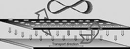
The following solutions can be found in the market: The most common nozzle systems are based on perforated plates, where the openings can have different sizes and design. At some systems, the outflow of gas is realised by small-sized nozzles only, whereas others have large openings realised as perforated plates (Figure 1). Identical in both systems, however, is that the used gas is only drawn off at the sides (front and back) of each zone. Therefore the gas transfers heat to the cold PCB where it cools down and then has to move across the entire board to circulate back for re-heating.
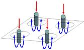
Another quite common air flow system works with small pipe nozzles, which are located in an opening of a larger diameter (Figure 2). The hot air flows through these tubular nozzles to the board. The backflow goes through the openings directly above the pipe nozzles. The important advantage of this system is that the gas has to move only short distances at the assembly. The disadvantage, however, is that the areodynamic resistance of these nozzles is considerably higher than at a system with perforated plates. Therefore, the amount of circulating gas is smaller. The maximum fan capacity of this system is limited by the small tubular nozzles and the resulting higher flow velocity which causes a risk of blowing off the components.
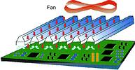
A third air flow system - slot nozzles - is available (Figure 3). These slot-designed nozzles are installed traverse to the conveyor direction. The inner case is designed to distribute an even amount of hot air to the assemblies at the entire working width. The slot directly beside the outflow is used as an intake for the exhausted and cooled gas. Therefore the distance of gas flow circulation for heating up the board is very short and energy transfer very efficient. The remarkable advantage, however, is that the slot nozzles have a much larger opening which creates less resistance to the gas flow and allows a much higher gas volume to be circulated without blowing off the components. Based on this construction a decisively higher energy density is achieved in the process zone.
Everyone has already had experience with hair dryers: there are models available which use high temperature at a low air volume and other models with a strong air stream at low temperatures. With the latter the warm-up is smoother and the risk of damaging the hair is much smaller.
The same applies to forced convection reflow soldering systems where the heating of the assemblies is very much dependent on the volume of circulated gas and its temperature. If for warming up a heavy component a certain gas temperature is required, then small components on the same board and temperature-sensitive components such as sockets may reach considerably higher temperatures. The difference in temperature (the Delta T) between the heavy components and the smaller components gets larger the higher the process temperature gets.
In the following we will show the practical consequences of heating an assembly with the different methods by means of a temperature profile. For this test series we have used an 8-layer PCB with 2,5 mm thickness. For temperature measurement thermo-sensors were installed under a PBGA 256, at a PLCC 68 and on the top surface of the PCB. A fourth sensor was used for checking the process gas temperature in the zones.
The reflow soldering systems used for this test were two machines with the same length (3 m) of the heating zone, each consisting of four pre-heating zones with top heating only and the peak zone with top and bottom heating. One of the systems was equipped completely with perforated plates as air flow system, the other system was equipped with slot nozzles in all zones. The temperature profile was set to reach pre-heating temperature of 170°C max and a peak temperature of 200°C min. The speed was adjusted to 90 cm/min and identical on both systems.
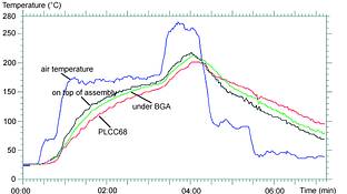
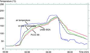
Temperature profile 1 (Figure 4) was measured on the oven with perforated plates in the entire process zone. To reach the correct temperature at the assembly, a pre-heating temp. of 175°C and a peak zone temp. of 270°C was required (chart 1). The result of these settings was 201°C at the PLCC 68 (as coldest spot) and 217°C on the board's surface. The temperature difference Delta T therefore was 16°C.
The demand for a minimum temperature of 200°C was fixed arbitrarily. Depending on product, components or even production, minimum temperatures of 205°C, 210°C or higher are required. If a minimum of 210°C is neccessary, the temperature on the hottest spot will be 226°C. It is only logical that with higher minimum temperatures and Delta T, the stress on the components and thus the risk of damage constantly increases. That a gas temperature of 270°C in the process zone is not very unusual for an oven with perforated plates is confirmed by suppliers of forced convection reflow soldering lines.
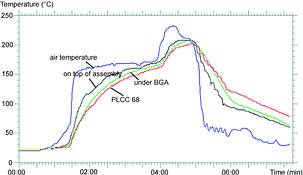
After this test a temperature profile was taken in a reflow oven with exclusively slot nozzles in all heating zones (Figure 5). Setting for the pre-heating zone was 170°C and 225°C for the peak zone. With these pre-set temperatures the PLCC 68 was warmed up to 202°C, while the maximum temperature of the entire board was 210°C, thus, the Delta T was 8°C only. If a minimum temperature of 210°C was required, the hottest spot would still be below 220°C. In the pre-heating zone the slot nozzles did not provide any considerable improvement. The reason for this effect is that the energy provided by perforated plates is efficient enough and the time period in the pre-heating zone is sufficient to warm up all components to an almost identical temperature. In the peak zone, where a fast temperature increase to above 200°C is needed, special requirements are requested for the air flow system and a slot nozzle system offers the highest efficiency.
In this case, the use of slot nozzles results in a reduction of process temperatures in the peak zone by 45°C, which leads to a reduction of maximum board temperature to 210°C and therefore a DT of 8°C only. This means considerably lower thermal stress for all components.
For the third test run we used a machine with the possibility of setting two different temperatures in the peak zone (SMT Quattro Peak). The first section of the peak was set to a higher temperature and the second section of the peak to an approx. 20°C lower. This allows all components a fast warm-up in the first section of the peak. In the second section with the lower temperature, heavy components can continue to warm up, whereas the smaller components (such as SMT plugs, sockets, switches) will not become overheated and reach as maximum the lower set temperature of this second section. The temperature profile is shown in Figure 6. The conditions and temperatures in the pre-heating zone are identical to Figure 5, the temperature setting in the peak zone was 235°C at peak section 1 and 215°C at peak section 2. The temperature of the PLCC remains unchanged at 202°C, however the temperature difference Delta T is reduced to 6°C as the maximum temperature of the entire board was at 208°C only.
Results
For this investigation such reflow profiles were realised, which represent today's state-of-the-art in the reflow process and which are based on standard (Ag-enriched Sn-Pb) solder paste. This paste has a melting temperature of 179°C and the boards are warmed up to at least 200°C. In a standard forced convection reflow oven, a peak set temperature of up to 270°C had to be selected in order to achieve this board temperature. In a high speed line with slot nozzles, this peak temperature could be reduced by approx. 40°C to a level of approx. 230°C only. At the same time, the DT was reduced by half, from 16°C to 8°C (with the SMT Quattro Peak even to 6°C only). This means considerably lower thermal and mechanical stress for the components. At a demanded temperature on the assembly of minimum 205°C, the maximum temperature should be only 211°C.
According to a prospective EC law, lead-free solder pastes should be introduced in the electronic industry before 1 January 2004. There will be advantages (lead-free, higher temperature stability of the solder connection etc), but also a number of disadvantages which have to be considered. The most important disadvantage for many manufacturer of SMD assemblies is the high melting temperature of about 220°C. For correct processing of lead-free solder pastes, the entire board has to be warmed up to around 240°C. The temperature level is approx. 40°C higher as presently normal. At standard reflow soldering systems (perforated plates, tube nozzles and similar) the process gas temperatures in the peak zone will then have to be set at least 50°C higher than today. For the board tested earlier this would result in a temperature in the peak zone of approx. 320°C. At the oven with slot nozzles and alternating blow-out and intake of process gases, the required set temperature in the peak, even under these circumstances, is only approx. 270°C. Since this temperature setting is already common today with some machines in standard reflow process, it is guaranteed that a modern high speed line with slot nozzles can be used without limitation for the handling of lead-free solder pastes. The assembly will not be subjected to higher thermal stress than in today's standard reflow ovens without slot nozzles!
More complicated is the situation with vapour phase soldering lines. Assuming that the required liquid is available at all and that it is acceptable (no new problems with environmental safety), a handling problem in the transition period will occur, when both leaded and lead-free solder pastes are used, because two different melting points have to be observed. This means that all liquids must be completely exchanged for the handling of the lead-free solder paste. Also all filters have to be cleaned carefully, as any mixing of different liquids will significantly influence the evaporation points. At a forced convection reflow soldering oven, a possible desired performance test is limited by the increase of the gas temperatures.
Energy costs
Most suppliers of convection reflow soldering ovens have realised that the 'Kreislaufwirt-schaftsgesetz' of 1997 (German law dealing with environmental matters) obliges to a low energy and low waste production, that in future even more stringent regulations have to be expected. It is remarkable that there are still units being offered, which - due to their construction - need an active cooling by means of water for certain temperature-sensitive parts of their reflow line. Thus, energy is used first to heat up the unit and then is wasted to cool down some parts of the line. Also, there is the need to remove the heat from the PCB assemblies after they have left the peak zone (reflow zone) and also from the flux trap. For this purpose, however, only a part of the total cooling energy is required.
The majority of the suppliers of reflow units, however, can do without water cooling. Even considering the fact that environmentally-compatible production becomes more and more important, ecological aspects still are often judged quite inadequately. The considerable difference in the operating costs, however, can mean much benefit to a company.
Summary
All forced convection reflow soldering systems work with hot air (or gas) only, the decisive question being however, how it is employed and which temperatures are required.
Modern forced-convection reflow soldering systems of different suppliers have impressive differences in the efficiency of energy transfer. In this study the lines with perforated plates or similar air flow systems require a process temperature of 270°C. For warming-up the same assembly to identical temperatures, a system with slot nozzles allows the process gas temperature in the peak zone to be reduced by up to 45°C.
These results have encouraged the German company SMT Wertheim to decide that all its forced convection reflow soldering systems (except for SMT 200°C) will be equipped in the peak zone with the slot nozzles patented by SMT. This guarantees smooth treatment of the entire assembly and provides process safety for high temperature lead-free solder pastes. In addition, the low energy consumption of the SMT lines due to its reduced operational temperatures means a reduction of operation costs as well as environmental compatibility.
Dr Klaus Brodt works at SMT Wertheim. He obtained his Ph.D. in the field of heat transfer at the Delft University of Technology, The Netherlands.
For further information contact Testerion, (011) 704 3020.


© Technews Publishing (Pty) Ltd | All Rights Reserved
 printer friendly version