


Resettable PTC thermistors are an attractive alternative to heat coils in telecommunication installations. These ceramic components provide superior protection and cut maintenance costs at the same time. Heat coils have traditionally been used in North America to protect central offices and customer premises equipment against current surges. But in modern automatic remote exchanges, heat coils cause problems because they create a permanent short circuit between the protected line and ground when tripped.
A heat coil works (Figure 1) on the same principle as a thermally operated fuse. The coil of defined resistance is wound around a bobbin, mounted on a shaft and soldered in place. Force is applied to the bobbin by a spring. When excessive current flows through the coil, heat is generated according to I2R, and the solder melts. The spring then presses the coil assembly against a ground contact, creating a permanent short circuit between the external telecom line and ground. Normal operation cannot be resumed until the module has been replaced manually - which is expensive, time-consuming and avoidable (Figure 1).
Typical resistances for heat coils used in North America are 4 and 20 Ohm. The rated current, ie the current at which the coil does not operate, is 350 and 150 mA respectively. The 4 Ohm/350 mA coil is more widely used, but the 20 Ohm/150 mA coil has been introduced to provide faster protection for more sensitive telecom equipment. The 20 Ohm coil has the disadvantage that its resistance may be too high and lead to an undesirable reduction in the range of the network. The response curves of current versus time for the two coils are shown in Figure 2. At 0,5 A, response times are approximately 100 s for the 4 Ohm coil and 20 s for the 20 Ohm coil. If the equipment to be protected has a resistance of only 100 Ohm, dissipation in the load can be calculated as 2500 W for the 4 Ohm coil and 500 W for the 20 Ohm coil (Figure 2).
The same protection can be achieved with ceramic PTC thermistors, with the added benefit that protection is reversible - without the need to replace the module. The switching characteristics of two 10 Ohm PTC thermistors (6,4 and 8,0 mm ceramic disks) with a rated current of 150 mA are shown in Figure 3. In the critical low-current range, the PTC thermistors are actually faster than both heat coils and dissipate 230 W (8,0 mm) and 110 W (6,4 mm).
Resistance and temperature
PTC thermistors are made of doped polycrystalline ceramic on a barium titanate substrate. In its pure form, this material has high resistance. Semiconduction and low resistance are obtained by doping it with materials of a higher valence. Free ions form part of the crystal lattice, which makes the ceramic conductive.
The resistance/temperature characteristic of the PTC thermistor is shown in Figure 4. Here the electrical load is kept as low as possible to limit change in resistance through thermal accumulation. As temperature increases, resistance decreases slightly (varistor effect) until the reference temperature TRef is reached and the thermistor trips, dramatically increasing its resistance.
Once the fault has been cleared, the reverse process occurs - the PTC thermistor cools down and returns to a state of low resistance. But the system operating current must be disabled first. Although less than 50 mA, this current can generate enough heat to keep the thermistor warm with a typical resistance of about 300 Ohm. To minimise disruption of service, the current should not be disabled for more than two minutes.
Balance requirements
Heat coils are typically selected to control imbalance between tip and ring wires. This is critical to network transmission quality since any imbalance leads to increased noise. PTC thermistors help maintain balance because they are supplied in matched condition. This means that all components on the same reel or in the same box will have a maximum difference in resistance of 1 Ohm, for example, as specified by the module manufacturer. Resistance will vary more across an entire shipment (Figure 5) because PTC thermistors, like heat coils, cannot be manufactured with such narrow tolerances. However, as ceramic PTC thermistors are resettable, balance must be maintained after they have cooled down. If normal operation is resumed within two minutes, resistance will return to within 1% of the original value at the same ambient temperature (Figure 5).
Failure modes
In heat coil operation, overcurrent leads to a short circuit between the telecom line and ground at the input to the protection module. The equipment is thus protected, but high currents resulting from power line faults continue to flow along the grounded telecom line. Once the fault has been detected and rectified, service personnel must be sent to the site simply to replace the protection module. And until the module is replaced, customers cannot make calls.
In contrast, the PTC thermistor internally dissipates the energy by switching to high resistance, reducing high currents to harmless levels (typically 10 mA). Protection of telecom equipment by thermistors is not only effective, but also reversible once the fault has been rectified and the thermistor allowed to cool down. Physical replacement of the module by service personnel is no longer necessary. This not only saves the network operator service charges, but can also lead to higher revenues since the line is out of action only for the time it takes to detect and rectify the fault.
New NAFTA standards for telecom protection
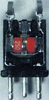
Telcordia, formerly Bellcore, recently revised the specifications for self-resetting, current-limiting thermistors in its Generic Requirements GR-974 for Telecommunication Line Protector Units (TLPUs). The conditions relating to imbalance, which are based on the slower and uncontrollable 'cooling' characteristics of polymer PTC thermistors, can be substantially improved by using ceramic PTC thermistors. Switching requirements can similarly be surpassed. To protect electronic equipment of increasing sensitivity against overcurrent, several carriers in NAFTA have already introduced fast-acting TLPUs based on ceramic PTC thermistors that feature low resistance and low transition currents. Previously, these installations could only be protected by heat coils of higher resistance, with the disadvantage of reduced range. A five-pin module used in Brazil is shown in Figure 6. It incorporates two ceramic PTC thermistors for fast, resettable overcurrent protection and a gas tube (T80-A250XF), all supplied by EPCOS. If varistors are used in addition, as in hybrid protectors, extra benefits result from the reduced forward current.
The resistance and the physical properties of the PTC thermistor as well as the mechanical contact in the module are important for compliance with Telecordia requirements. At constant current, a 20 Ohm PTC thermistor will trip faster than a 10 Ohm thermistor due to the increased dissipation in accordance with I2R, but will exceed the 20 Ohm limit at -40°C due to the varistor effect. Similarly, a small PTC thermistor will react faster than a larger one of the same resistance, as shown in Figure 3. Too large a contact area will cause the thermistor to lose heat through the contact surface and lengthen its switching time. The optimum solution is therefore a 10 Ohm PTC thermistor with a small volume and contact area. The formula for the ceramic material is also important. Ceramic compounds with reference temperatures of 80 to 85°C are typically used because the thermistors are operated at a lower temperature and will therefore trip faster.
| Tel: | +27 11 458 9000 |
| Email: | [email protected] |
| www: | www.electrocomp.co.za |
| Articles: | More information and articles about Electrocomp |


© Technews Publishing (Pty) Ltd | All Rights Reserved
 printer friendly version