


Poynting Innovations have been awarded a six month development contract with ANPC (Advanced Navigation & Positioning Corporation), a USA-based company. Poynting will develop an antenna for its transponder landing system (TLS), and will be involved in the design, testing and manufacturing of the antenna system.
Poynting will design, build and test an electrical prototype of a VHF and a UHF antenna that will be used as part of ANPC's Transponder Landing System. Pre-production prototypes will be delivered on completion of the contract. Ultimately, the antennas will be FAA-approved as part of the TLS and Poynting will manufacture the antennas for ANPC.
The design
The VHF antenna is required to have a gain of at least 6 dB between the elevation angles of 1° and 7° and a front to back ratio of 20 dBs. The antenna that was designed consists of an open-air collapsible structure that supports a 3 dipole array. The collapsible structure is important, as this enables the antenna to be compactly stored for transport purposes. (See Figure 1).
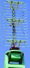
The client required that the antenna be able to operate within specifications when coated in a 13 mm layer of ice. In order to achieve this, the dipole elements were coated with a layer of resin, which has electrical properties similar to that of ice. This protective layer makes the antenna less susceptible to the deleterious effect that ice has on the electrical performance of the antenna. The UHF antenna has similar specifications to the VHF antenna. The UHF design consists of a 2-element dipole array, mounted in a box-like reflector. The antenna is covered by a radome to protect it from environmental effects, such as ice and snow.
The antennas were designed using SuperNEC - an EM simulation package developed by Poynting. SuperNEC has a new feature to simulate antennas coated in a dielectric sheath. This was used to determine the electrical properties and thickness of the coating on the VHF dipoles. The rationale was to find an antenna coating such that when a layer of ice was added to the antenna, the antenna still performed within spec.
The TLS is actually a precision tracking system. The system interrogates the aircraft's air traffic control radar beacon transponder and determines the location of the aircraft from the transponder reply to two ground-based sensors. The transponder's location is resolved in azimuth, elevation angle and range. The system then provides guidance to a tracked aircraft. TLS guidance is delivered to the aircraft by emulating ILS (instrument landing systems) signals. When receiving TLS guidance, the pilot flies the aircraft as if on an ILS approach. No new aircraft equipment or avionics are required to benefit from TLS. The aircraft must be equipped with a standard ILS receiver and an ILS display.
Benefits of the TLS
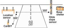
The TLS is tolerant to terrain that would otherwise preclude an ILS installation. A powerful calibration procedure enables the system to cope with uneven and mountainous topography. No new avionics are needed. The TLS adds value to the legacy installed-base of ILS. To the pilot, there is virtually no difference in flying the TLS versus an ILS. All the TLS components are located in a small footprint on the airport property. Figure 2 shows the most common configuration for a TLS installation. The sensors can span the runway, and are connected by underground cables. The base shelter contains all the electronics. The system's configuration is extremely flexible and is easily customised to each site's requirements. Components can be placed entirely on one side of a runway or can sit astride the runway. The TLS system software makes this unique configuration variation possible.
Poynting Innovations supplies industry with electromagnetic engineering research, development services and products. For additional information see www.poynting.co.za or contact 011 262 5155.


© Technews Publishing (Pty) Ltd | All Rights Reserved
 printer friendly version