


For the construction of highly efficient switch mode power supplies, it is important to know the losses in the core and winding of inductive components. Conventional calculation methods only provide reliable values under specific conditions and with exact knowledge of the core materials. Therefore, Würth Elektronik eiSos developed REDEXPERT, a new model that is available to design engineers as an easy-to-use development tool.
In switch mode power supplies, the power inductor serves as a storage component. It stores energy in the form of a magnetic field during the on phase of the switching controller and discharges the energy to the load during the off phase.
Generally, the storage inductor consists of a copper wire winding and a core with magnetic properties. The power losses result partly due to the DC resistance (RDC) of the windings. However, skin and proximity effects in the winding and hysteresis and eddy current losses in the core also cause losses. These are collectively referred to as the AC resistance (RAC) of the inductor, which primarily depends on the operation frequency.
There are several methods to determine these effects in magnetic components. However, to achieve even approximate values for these losses, complicated calculations such as the Dowell method are required.
Core losses
We know from electromagnetic physics that if a magnetomotive force is applied to a coil, over time it induces a magnetic flux Ø(t). At any time, the magnetic flux density β is always proportional to the field strength H:
β(t) = μr ƒ μo H(t)
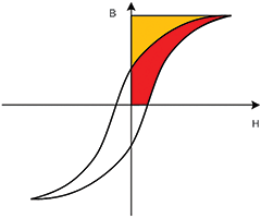
β is the magnetic flow density (Ø/A), μr is the permeability of the material, μo the permeability of the air and H the magnetic field strength. β is measured, while H is increased. The relationship between β and H is non-linear and shows a hysteresis (hence the name hysteresis curve). The hysteresis shows the characteristics of the core material that cause power loss in the coil core. Figure 1 shows the typical BH curve for a sinusoidal excitation of the core.
The energy loss of one switching cycle in the core equals the difference between the magnetic energy applied to the core during the on phase, and the magnetic energy released by the core during the off phase. This is caused by molecular magnets, which during the off phase do not return on their own into their initial position and instead have to be reset using energy.
Applying Ampère’s and Faraday’s laws, the energy in the core can be expressed as follows:
E = ƒH dB
The second type of core losses result from eddy currents that are induced by a time-varying flux (dØ/dt) in the core material. According to Lenz’s law, a current is induced due to the change in flux. The current then induces a magnetic flux that opposes the original flux. This eddy current flows through the conductive core material and generates I²R losses.
Determining the losses
Initially core losses were determined using the power equation, also known as the Steinmetz equation:

Here, Pv are the core losses (due to hysteresis and eddy currents) for each unit of volume, f the frequency, βpk the maximum flow density of a sinusoidal excitation and K, α and β the constants that are derived from the core loss graph.
The main disadvantage of the Steinmetz equation is that it mainly applies for sinusoidal excitations. However, in power electronics applications, the coil is mainly exposed to non-sinusoidal magnetic flux waveforms. There are certainly other models that try to solve the problem of non-sinusoidal waveforms by separating the hysteresis and eddy current losses, yet the empirical Steinmetz equation has proven to be a useful choice and, for sinusoidal magnetic flux waveforms, offers high accuracy combined with simple application.
That is why there are extensions for this power equation, intended to make it usable for non-sinusoidal magnetic flux waveforms as well. An extension called MSE (Modified Steinmetz Equation) has been applied for some time to estimate the core losses using the Steinmetz equation for non-sinusoidal waveforms:
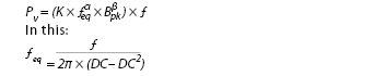
Feq is the equivalent frequency relating to the change in the duty factor for non-sinusoidal waveforms.
Due to the disadvantages inherent to MSE, GSE (Generalised Steinmetz Equation) was developed. It is shown in the following equation:
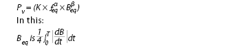
GSE and MSE core loss graphs are also based on a sinusoidal excitation. The following main disadvantages apply to the Steinmetz model and its extensions: Firstly, the empirical data provided by the core manufacturer has to be used for the creation of core loss graphs. Manufacturers of passive components have no influence on the test setup. Because core loss graphs are also based on data that results from a sinusoidal excitation, the pulse and the triangle waveforms are not accurate enough.
Due to errors during parameter conversion, the extension of the Steinmetz model only works optimally with a duty factor of 50% and an unlimited frequency range. This method is limited to certain materials, and due to the high complexity during the estimation of the magnetic path length, the estimation of the core losses using existing models for iron powder and metal alloy materials is not only complicated, but also delivers strongly fluctuating accuracy. For components that consist of several materials, an estimation of the losses is impossible.
And the final point of criticism for the described approaches is that alternating current losses of the winding are not taken into account.
New alternating current loss model
Würth Elektronik eiSos developed a new model to allow developers to choose the right inductance with high effectiveness for optimising their circuit. It is based on empirical data that is generated using a real-time application setup. Here, the overall inductance losses are separated into alternating current and direct current losses. Power losses due to the direct current in the coil windings are referred to as direct current losses. The power losses due to the magnetic modulation within the coil and the core are referred to as alternating current losses.
Empirical data is recorded by a DC-DC-converter, as shown in Figure 2. An oscillating voltage is applied to the inductor, then the input power Pin and the output power Pout are measured. Based on this, PLoss = Pin - Pout is estimated and the alternating current losses of the coil PAC are separated.
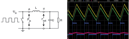
To be able to record the empirical data, this operation is measured for different sets of parameters – for example, fluctuations of the magnetic modulation, frequency, ripple current etc. Based on this, the model for calculating the alternating current losses is created:
PAC = Δƒ (I, freq, DC, k1, k2)
The hysteresis curves shown in the datasheets for typical core materials represent the magnetic modulation from positive to negative of the core using a sinusoidal waveform. Here, the hysteresis curve indicates the energy loss shown in Figure 3(a). However, for a switch mode power supply application, the core is generally driven by a significantly smaller square waveform with maximum flow density that, due to the core losses, is limited to a smaller hysteresis curve (Figure 3(b)).
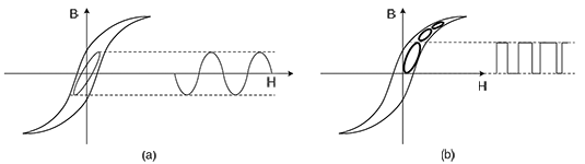
Power loss depends on how often per second the hysteresis curve is traversed. This means the hysteresis losses depend directly on the frequency. The hysteresis curve changes its shape if the waveform, drive current, drive voltage or temperature change. These fluctuations make an exact prediction of the core losses extremely difficult.
The smaller hysteresis curve depends on the voltage across the inductor. This smaller hysteresis curve is used exactly at the operating point to generate empirical data for the alternating current loss model from Würth Elektronik. It has proven to be robust and precise for a wide range of parameters such as frequency, ripple current and duty factor.
Evaluation of Würth Elektronik’s AC loss model
Because the empirical data is solely based on real-time parameters, the losses for any given duty factor can be accurately determined using this model. The model works very accurately for a wide frequency range (10 kHz to 10 MHz), because the constants of the power equation were determined for a wide range, taking into account the magnetic modulation.
Even minimal changes in the core material or winding structure are taken into account, and the model is valid for components consisting of more than one material. It allows precise determination of losses for iron powder and new ‘metal alloy’ materials. The model is valid for any core shape and winding structure, and includes AC winding losses.
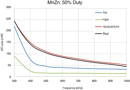
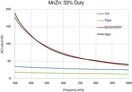
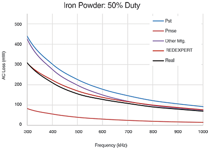
Würth Elektronik’s model has been exhaustively validated and compared with existing models and measured data. The alternating current losses for different materials, such as WE-Superflux, iron powder, NiZn, MnZn etc., are measured across large duty factor and frequency ranges and compared with theoretical models.
Figures 4 to 6 show the core losses determined using the Steinmetz power equation (Pst), modified Steinmetz equation (Pmse) and the generalised Steinmetz equation (Pgse). REDEXPERT is the alternating current loss resulting from the calculation using Würth Elektronik’s AC loss model. ‘Real’ is the measured AC loss.
Application in the online platform
Using the described approach, Würth Elektronik developed the REDEXPERT online platform (Figure 7). It allows developers to quickly compare inductances and to very easily choose the most suitable power inductor for the respective applications. The user enters input and output parameters into the required topology and REDEXPERT calculates the inductance values and shows the matching inductances (Figure 8).
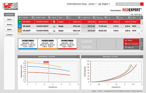
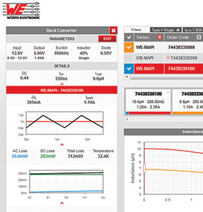
Würth Elektronik eiSos offers a comprehensive range of power inductors for all kinds of applications, therefore users should be able to find a component suitable for their specific conditions by entering the required parameters. The integration of the new AC loss model into REDEXPERT eliminates the complex and erroneous calculation of AC losses. The accurate results for all AC losses can also be used to estimate temperature deltas.
Currently, REDEXPERT supports three topologies for which the customer can select the component for the application: step-up converters, step-down converters and SEPICs (singe ended primary inductance converters). Furthermore, there is a loss calculator that computes the losses for power inductors independently of the topology. REDEXPERT is a web-based online platform ( www.we-online.com/redexpert/), therefore users neither need to download nor update it.
For more information contact Jason Page, Würth Elektronik eiSos, +27 71 259 9381, jason.page@we-online.com, www.we-online.com
| Email: | lesley.havenga@we-online.com |
| www: | www.we-online.com |
| Articles: | More information and articles about Würth Electronics South Africa |






© Technews Publishing (Pty) Ltd | All Rights Reserved
 printer friendly version