


Cypress Microsystems described in the first part of this article how it turned the tables on the whole process of choosing a microcontroller with its PSoC (programmable system on a chip) system. It continues this discussion with the examination of how one actually goes about creating a real design with the PSoC microcontroller.
The process begins with the Device Editor. Figure 1 shows the PSoC device editor user module selector. This screen allows the user to browse through the user modules (peripherals), listed on the left of the screen, and add them to the list of required modules. A gauge to the right shows the resources that are used as user modules are selected.
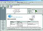
Each user module has a complete data sheet associated with it. This gives the designer all details they may require when designing their circuit. Most importantly, it also gives details of the APIs that will be created once the device has been compiled. In order to assist with the firmware design, the data sheet also has example assembler code that shows typical usage of the user modules via the APIs. This code has been written so it can be cut and pasted into the engineers' firmware - an excellent feature since it reduces the time taken to understand the syntax of the API.
Place and connect
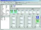
Once the selection is complete, the user modules must now be placed onto the PSoC silicon and interconnected as required. This procedure is carried out using the Place user modules page (Figure 2) of the PSoC device editor (invoked by clicking the icon). Figure 2 shows the digital and analog PSoC block arrays. This array has a total of eight digital PSoC blocks and 12 analog PSoC blocks. The user modules, that were previously selected, can now be placed into the PSoC block array. Once positioned the blocks can be interconnected, eg, output of comparator to input of timer, by simply clicking on the relevant input/output signal and selecting the appropriate interconnection from the list in the pop-up menu. Also on this page, any global resources that may be required in the design can be selected in the left hand menu. Items such as CPU system clock, sleep timer frequency and op-amp bias can be configured from this.
Once the user modules have been correctly positioned and connected together, the final stage of the microcontroller design can be completed. This final task requires the user to connect the user modules to the pins of the chip itself. This task is performed on the specify pinout page (Figure 3) of the PSoC device editor.
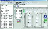
By simply clicking on the device pin, the drop-down menu allows selection of drive level required (High-Z, pull up, pull down, strong) and internal node that is to be connected to the pin. Also, this selection process can be carried out using the PortPin menu on the left of the screen.
Once the pinout has been selected the project can now be compiled. The compilation process for the PSoC device (not the firmware) is invoked by clicking the icon. The compilation process builds the required boot and main assembler files. The boot.asm files' primary function is to configure the PSoC, initialise 'C' variables, organise interrupt tables, define the reset vector and call the main (_main) routine. A skeleton main.asm file is also created which is where the user begins writing their firmware.
Data sheeting
Once the device has been compiled this is the most exciting time for the engineer, for he/she has just designed their very own semiconductor device. It is unique to their application, and it is now possible to generate a data sheet for the new creation. By pressing the data sheet icon, the engineer generates a data sheet for the new device. This documentation is ideal as it reduces the time taken to create design specifications. All the information required to describe the new chip is detailed in this data sheet.
Now that a microcontroller has been created which has the correct number of peripherals included to perfectly fit the application targeted, work can begin on developing the firmware. The M8C processor executes the firmware. All coding of the firmware is carried out in the application editor. The default editor uses assembler but the user can invoke the 'C' Compiler from the Tools option visible on the menu bar at the top of the screen. Standard calling conventions are recognised in the 'C' Compiler and Assembler. An underscore is implicitly added to 'C' functions and variables.
Test and debug
With the development of firmware complete, testing and debug can be carried out. The PSoC designer debugger screen, along with the in-circuit emulator (ICE) pod, allows the engineer to test their firmware in a physical system while providing an internal view of the PSoC device. Debugger commands allow the engineer to read and write program and data memory, read and write I/O registers, read and write CPU registers, set and clear breakpoints and provide program run, halt and step control.
Other features include a trace buffer that can capture registers and memory locations of interest. The ICE connects into the parallel port of a PC and allows the engineer to debug their PSoC whilst connected to the target system. The ICE also has the capability to program single PSoC devices.
As can be seen in the design flow, the PSoC integrated development environment allows the engineer to design and develop his or her own unique microcontroller quickly and efficiently. The user module approach allows microcontroller peripherals to simply be 'drag and drop' items. Each peripheral can then be interconnected, not only to each other, but also to the device pins, by the click of a mouse. Once the device has been constructed, the firmware is developed using either assembler or 'C'.
The interface between the firmware and hardware is made simple by the generation of application programming interfaces for each of the peripherals. This means that the software developer does not get involved with the detail of configuring the PSoC blocks at a low level.
Summary
Cypress Microsystems has shown that it has the capability to enter the 8-bit microcontroller market with a device that has differentiators from the standard offering in this market. Its solution uses state of the art technology (a unique Flash process called SONOS) to provide the engineer with a flexible solution to the 'perfect fit' microcontroller design problem. Cypress Microsystems can provide this capability at extremely low cost, offering the PSoC Designer tool free over the Internet. Moving forward, this device is seen as an Internet-based product in that user modules can be downloaded via the Internet and engineers will have access to an ever-increasing number of peripheral components free of charge.
For more information contact Simon Churches, Arrow Altech Distribution, 011 923 9600, [email protected]
| Tel: | +27 11 923 9600 |
| Email: | [email protected] |
| www: | www.altronarrow.com |
| Articles: | More information and articles about Altron Arrow |


© Technews Publishing (Pty) Ltd | All Rights Reserved
 printer friendly version