The new generation of wireless devices, PDAs, Internet audio players and other appliances demand accurate battery capacity monitoring. The improvement in feature content and complexity of these portable devices has had a dramatic impact on the battery and battery management.
The simple and inaccurate voltage-based capacity monitoring schemes of the past are no longer acceptable. The users demand to know the real available capacity. They need to know how many more audio files can be downloaded, how many more stock trades can be placed, and how many more calls can be made before the battery finally runs out. An inaccurate capacity gauge is both annoying and frustrating to the end-user.
A voltage-based capacity-monitoring scheme lacks the required accuracy for today's wireless applications. Lithium-ion and lithium-polymer batteries, for instance, have a relatively flat voltage profile in both charge and discharge directions. In fact, during a typical charge cycle, more than 70% of the charge time is spent in a constant voltage mode. This mode is responsible for replenishing more than 40% of the charge capacity. Similarly, on a discharge cycle, most of the capacity is available in a relatively narrow voltage range, from 3,7 down to 3 V.
To make matters worse, the available capacity also changes as a function of self-discharge, cell ageing, temperature, and discharge rate or profile. The latter is particularly important in wireless applications. For instance, the discharge profile of a GSM handset depicts a pulse of over 1 A in amplitude and around 25% duty cycle. During standby mode the current is reduced to less than 10 mA.
To solve the challenges of precise capacity tracking and monitoring, Texas Instruments has developed a family of accurate battery monitor devices. These devices use the coulomb counting method in order to provide the user with accurate and reliable information about the battery's state of charge. The purpose of this report is to provide the basics of building an accurate gas-gauging feature using these devices.
A variety of different battery monitor ICs are available from TI that offer different features. Some differences to note are: memory; current sense inputs; charge/discharge count rate; offset calibration; offset compensation; temperature reporting resolution; programmable output pin; packaging.

System components
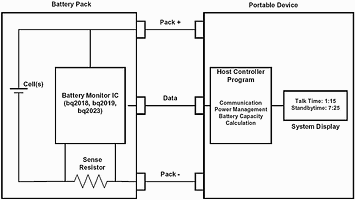
Measuring battery charge and discharge current and reporting state of charge to an end user requires several components (see Figure 1). These include:
* A battery monitor such as the bq2018, bq2019, or bq2023: Battery monitor ICs contain a high accuracy coulomb counter, temperature monitor, communication interface, and other functions.
* A current sense resistor: The low-value (typically between 10 to 20 mΩ.) sense resistor provides a means for the battery monitor to measure the current flowing into or out of the battery. The battery monitor senses the voltage across this resistor.
* A host controller with one free general-purpose I/O for communication: The host controller is required to provide intelligence to the battery monitoring set-up. The host controller handles all communication with the battery monitor IC. Since the HDQ and SDQ communication protocols are asynchronous one-wire based, a general-purpose I/O is dedicated to handle the communication flow. The host also performs calculations with data read from the battery monitor to determine the battery's state of charge.
What is coulomb counting?
Coulomb counting simply means measuring the charge input to and subsequently removed from the battery. In order to accomplish this, first the charge and discharge current is measured across a low-value series sense resistor between the negative terminal of the battery and the battery pack ground contact. The voltage drop across the sense resistor is then integrated over time to provide an accurate representation of the state of the charge of the battery.
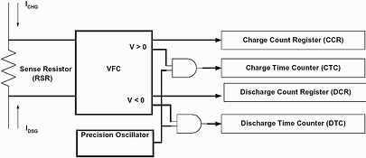
Battery monitor devices from Texas Instruments use a highly accurate and low-offset voltage to frequency converter (VFC) to measure the voltage drop across the sense resistor. The output of the VFC is then converted to an accumulated count in either the charge or the discharge register to represent the charge flow into and out of the battery. See Figure 2.

The VFC is connected such that a positive voltage is developed across the sense resistor when current is flowing into the battery (ie, charge). Conversely, a negative voltage is developed across the sense resistor, and thus the VFC inputs, when current is flowing out of the battery (ie discharging). Charge and discharge activities are accumulated in two independent registers: charge count registers (CCR) and the discharge count register (DCR).
The VFC is designed to count at a fundamental rate. This rate, also known as the VFC gain (or simply GVFC throughout this app note), provides a conversion factor between the output of the VFC to the input voltage. The data sheet for the battery monitors report the VFC gain as an Hz/V value. This simply means that a given input voltage will produce a certain number of counts in some period of time. For instance, the bq2018 has a typical VFC gain of 22,2 Hz/V while the bq2019 has a typical gain of 90,51 Hz/V. This means that if the bq2018 CCR incremented one count every second, the input voltage would be 45 mV (1 sec/22,2 Hz/V). An increase of CCR every second in the bq2019 would mean an input voltage of 11,05 mV (1 sec/91,1 Hz/V).
In addition to the charge/discharge count register, the battery monitors have two time registers, charge time counter (CTC) and discharge time counter (DTC). The CTC runs while the battery charges, and DTC runs while the battery discharges. Only one timer will always be running at a rate of 4096 counts per hour, provided the registers have not experienced a rollover.
Sense resistor selection
The sense resistor must be sized properly to measure the entire range of charge and discharge currents in the application within the limits of the battery monitor. The items to consider include:
* The maximum potential of the SR input as specified in the IC's data sheet. This limit for the bq2019, for instance, is -100 mV to +100 mV. Therefore charge/discharge currents through the sense resistor must not produce a voltage greater than ±100 mV.
* The VFC gain as specified in the IC's data sheet. The bq2018, for instance, counts charge and discharge at a rate of 12,5 mV per hour. Signals less than 12,5 mV require greater than one hour to resolve. The designer should consider the resolution vs time when selecting a sense resistor.
* The sense resistor must also handle the power dissipation of all charge and discharge activity.
Calculating charge and discharge time
The host system can calculate the change in time by reading CTC/DTC at time zero, designated as CTC0/DTC0, and then reading them again some time later, designated as CTC1/DTC1. The change in time, in seconds:
Δt (s) = [(CTC1 - CTC0) + (DTC1 - DTC0)] * 3600/4096----------(1)
After Δt is calculated, the host system should store CTC1/DTC1 as CTC0/DTC0 for the next time period calculation.
The preceding discussion is meant to serve as a basis for the calculations to determine remaining capacity. The charge/discharge count registers, VFC gain, and the change in time are three of the fundamental values necessary to calculate remaining capacity and time to empty.
Calculating average current
The host system will not be communicating with the battery monitor on a continuous basis. The microcontroller spends most of its time controlling other system components. But when the battery monitor is accessed, one of the values the host microcontroller may be interested in calculating is average current during the last time period. This discussion assumes that the host has communicated with the battery monitor and either stored initial values or performed maintenance to clear the CCR/DCR and CTC/DTC registers. Either way, designate the initial readings as CCR0/DCR0 and CTC0/DTC0. The host should read the CCR/DCR and CTC/DTC registers, reference below as CCR1/DCR1 and CTC1/DTC1. The average current during the last time period:
IAVG (A) = [(CCR1-CCR0) - (DCR1-DCR0)]/(Ωt * GVFC * RSR)----------(2)
Δt (s) is calculated from equation (1) or calculated from the host controller's internal timer, GVFC is the VFC gain (Hz/V), and RSR (Ω) is the sense resistor. A negative IAVG indicates discharge and a positive IAVG indicates charge.
This value can be used to calculate the time to empty at the discharge rate calculated.
Calculating accumulated current
Accumulated current is used to calculate the absolute remaining capacity of the battery. It requires knowledge of the capacity at some time. The battery design capacity is typically used when the battery goes through its first discharge from full. After that, a simple algorithm can be generated to learn the true battery capacity. The accumulated current during the last time period:
IACC (As) = IAVG * .t = [(CCR1-CCR0) - (DCR1-DCR0)]/(GVFC * RSR)----------(3)
After the calculation for IAVG or IACC is complete, the host system should store CCR1/DCR1 to CCR0/DCR0 for the next time period.
Calculating the remaining capacity
Remaining capacity is the entire goal of gas gauging. This value can be manipulated in a number of ways to display for the end user. It can be presented as a percentage of total capacity, which is either the design value, or the learned value, or used to calculate time to empty, which is detailed below. The remaining capacity calculation:
RM1 (As) = RM0 + IACC----------(4)
IACC (As) is calculated from equation (3), RM0 (As) is the last calculated remaining capacity. After the calculation for remaining capacity, the host system should store RM1 to RM0 for the next time period.
Calculating the time to empty @ rate
The basic assumption behind this calculation is that the user is interested in the time to empty at the average current consumption during some time period. This might require that IAVG, calculated in equation (2), be calculated at a longer time period than IACC. More accurate average current, will result in more accurate time to empty calculation. The time to empty at IAVG rate calculation:
TTE@RATE (s) = RM1/IAVG----------(5)
IAVG (A) is calculated from equation (2), RM1 (As) is the remaining capacity calculated in equation (4).
Other battery parameters
Other battery parameters include temperature and voltage. All TI battery monitors measure and report the die temperature to the host controller.
Most host controllers monitor the battery voltage through an ADC channel. By measuring the battery voltage, the host controller can signal the end user when the battery has reached its end of discharge voltage. This voltage, which varies from design to design and by cell type, is the absolute minimum at which the battery should be operated to maintain cell life.
Summary
This article has provided an overview of the components necessary for gas gauging a battery with the TI battery monitors. A very simple system and understanding of some basic equations should allow for a basic gas gauging application to be built. The article has not covered some other steps needed to create a more sophisticated gas-gauging algorithm. These topics include capacity learn cycles, charge efficiency correction, self-discharge correction, VFC gain error over temperature and voltage, VFC offset, and device temperature reporting. Proper handling of these topics results in a remaining capacity calculation that is extremely accurate across a system's temperature and voltage range.

© Technews Publishing (Pty) Ltd | All Rights Reserved