


Direct Digital Synthesis (DDS) is a technique for generating waveforms of precise shape and frequency. The use of DDS in function generators has increased the performance of these instruments while reducing their cost. This article examines the DDS technique and reviews the benefits of its use in waveform synthesizer instruments.
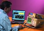
Function generators are a useful general-purpose instrument for many areas of the electronics design and manufacturing industries. They can generate a number of different signals at frequencies and amplitudes for use in evaluating the operation of new circuits, replacement of clock signals, manufacturing test of new products, and many other purposes.
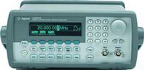
The design of function generators has evolved many times since the first sine-wave generators, and in today's digital world, most new function generators, like the new Agilent 33220A, are being designed using DDS. As the name implies, DDS uses digital circuitry for a large portion of its operation, bringing with it many of the advantages of digital operation. Only in the last stages of synthesis is the signal converted to the analog domain, in many ways reducing the complexity and increasing the stability of the function generator.
The DDS is essentially a wide multibit counter running at a constant high frequency. The counter is allowed to 'wrap' around through zero when it overflows, with a very large control word setting the size of the counter step. The high order bits of the counter are used to address a memory device holding a digital record of one cycle of the waveform being generated. With each 'tick' of the high frequency clock, the counter makes one step, a new address word is generated for the memory, and a new waveform data value is sent to the digital-to-analog converter (DAC). The DAC output is the sampled analog waveform, which is sent through reconstruction filters before being output from the generator.
One of the first advantages of DDS is that the frequency of the output signal can be as accurate as the crystal controlled oscillator used as a reference signal to the generator. This reference signal may be a crystal oscillator (XO), or for more accuracy, a temperature compensated crystal oscillator (TCXO) in the instrument itself. These can offer better than 1/10th PPM frequency accuracy. In many cases, the instrument may also be capable of being frequency-locked to an external laboratory frequency reference for very high accuracy signal generation.
On many lab benches, another instrument like a frequency counter may have the most accurate oven-controlled clock oscillator, and its output reference signal may be used as a reference signal for a DDS function generator. In other precision measurements labs, a 10 MHz standard frequency reference signal will be 'plumbed' to each bench for use for this purpose. The DDS circuit, due to its digital nature, can lock to this frequency and provide signals as accurate as the reference standard.
The second advantage of DDS is related to the first: a DDS generator can generate frequencies with very high precision. The digital circuitry of a DDS signal generator can have as much frequency precision as the digital circuitry implements. If the DDS circuit has a 48-bit counter, it can offer up to 48 bits of frequency resolution, or about 3 parts in 10 to the fifteenth power, and some DDS synthesizers use counters with more bits and even higher resolution.
This high resolution means that the function generator is able to exactly generate a desired output frequency and it also means that the generator can make very precise changes in frequency. This is especially useful in evaluating timing circuits for communications, mass storage and similar applications. It is not unusual to find DDS generators that can generate tens of megahertz with microhertz resolution.
With so much of the waveform generated digitally, it is not surprising to find that the modulation, sweep and burst-generation functions in the function generator are also under digital control and can also be set up with high precision. Not only frequency and timing, but phase and amplitude can be set and changed exactly.
A third advantage of DDS is that the function generator may reproduce virtually any waveform if it has RAM waveform storage. The DDS generator operates by 'playing back' a waveform stored in its memory. If the memory is read-only memory, then only those waveforms stored in the ROM can be generated. Typically, a Sine, Square, Triangle and similar waveforms are built into every function generator. But suppose the application requires a Square Wave with a 10% duty cycle, or a triangle wave with 58% symmetry rather than 50%. If the DDS circuit has a RAM for waveform storage, the controller circuit can write any wave shape into the RAM and cause it to be replayed through the synthesizer.
So the function generator now is capable of far more than the traditional function generators could do. Variable symmetry waveforms are now standard functions, and a variety of unusual waveforms can also be built-in, such as exponential rise and fall, or sync pulses, etc.
Taking this RAM concept one step further, suppose you have some particular waveform that is unique to your testing needs. Some function generators allow customer-specified waveforms to be loaded into the RAM of the DDS engine and to be played back by the synthesizer. This brings the function generator the additional capability of generating an 'arbitrary waveform', a waveform of virtually any shape. This useful function is usually supported by software that is able to read waveforms from a variety of sources, including Matlab, MathCad, Excel and similar software file formats, as well as oscilloscope waveform capture files.
New function generators have capitalised on the advantages of DDS, and have been able to combine in one instrument the functions previous found only in separate instruments. The DDS-based function generator now performs not only the functions of a function generator, but also of an arbitrary waveform generator. On top of adding ARB capability, some are capable pulse generators as well.
So the next time you examine the specifications for a function generator, do not be surprised to find a low-drift, high precision instrument based on DDS technology.
How a DDS operates
The direct digital synthesizer (DDS) circuit is a digital technique to generate an analog signal. The entire circuit operates from a fixed-frequency clock ('clock signal') that runs continuously at a rate at least twice the highest frequency to be generated.
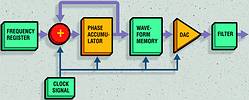
At each clock pulse, a frequency word from the frequency register is added to the contents of the 'phase accumulator' register, and the new number is stored in the phase accumulator. These components (frequency register, adder and phase accumulator) may be very wide registers, possibly 48 to 64 bits of resolution, which yields the very high-resolution frequency control possible using this circuit. When the phase accumulator overflows, the remainder is retained to calculate the phase of the first sample of the next cycle.
The lower-order bits from the phase accumulator are also used as the address lines for the waveform memory. The address lines represent the instantaneous phase of the waveform being played back by the DDS circuit. A data value representing the amplitude of the waveform at this phase is read from the waveform memory and delivered to a digital to analog converter (DAC) which puts out an analog voltage corresponding to the amplitude of the waveform at this phase.
The waveform memory contains one cycle of the waveform to be synthesized. In some DDS circuits other forms of phase-to-amplitude converters replace the waveform memory, but for a general-purpose function generator, the use of RAM in this circuit allows many different waveforms to be synthesized by changing the RAM contents.
The final, but essential element is the low pass filter that removes sampling effects from the signal. The design of this filter is somewhat simpler than in many synthesizers because the sample clock runs at a single, fixed frequency.
About the author:
Christopher Kelly received his Bachelor of Science from the University of New Mexico and an MS from Colorado State University. He is a design engineer in the Basic, Emerging and Systems Technologies operation at Agilent Technologies. Kelly holds four patents in the field of data acquisition and recently completed the design of the Agilent 33220A function generator.
| Tel: | +27 12 678 9200 |
| Email: | [email protected] |
| www: | www.concilium.co.za |
| Articles: | More information and articles about Concilium Technologies |


© Technews Publishing (Pty) Ltd | All Rights Reserved
 printer friendly version