The use of optical fibres for distributed temperature sensing is now a well-established technology. In conventional temperature measurements, a sensor, such as a thermocouple or platinum resistance probe, is needed for each point of interest.
For applications where large areas or long distances are involved, conventional systems become over complicated, bulky, unreliable and costly to maintain. An effective alternative solution is a distributed sensing system. The expression 'distributed sensing' is used to describe a technique whereby one sensor can give data spatially distributed over many thousands of individual measurement points. A single optical fibre has the ability to act as a distributed temperature sensor with potentially many thousands of individual measurement points.
This article discusses some of these possibilities in the light of technology currently available and the opportunities that exist for maximising the installed assets on the process plant and power cable system.
Technology development
Distributed optical fibre temperature sensing was first demonstrated in 1981 at Southampton University using techniques derived from telecommunications cable testing. The original work used special fibres that resulted in limited temperature range and distance cover but good response time and spatial resolution obtained.
Subsequent work, started in 1984, has provided a technology able to cover much longer distances and a wider temperature range using standard multimode and single mode telecommunications fibres. The instrumentation is used worldwide in the energy sector and other operational environments.
Although the technology is sophisticated, the use of optical fibres as sensors is very simple and opens up many areas of measurement.
DTS systems
Distributed temperature sensing (DTS) represents a powerful breakthrough in temperature measurement. Fast, accurate, high-resolution measurements are now practical. The DTS system is based on optical fibre technology that means that it can be used in a wide range of conditions including hazardous environments and electro magnetic interference (EMI) intensive areas such as in power cable monitoring.
The sensing cables are rugged, inexpensive, easy to install and low maintenance. If the sensor fibre is broken, it automatically identifies a break has occurred and reports the location. The system can also be set to stop the measurement immediately after a break occurs. Alternatively, if the sensor fibre is configured in a loop, the system can switch to single-ended measurement from both ends thereby avoiding any loss of data. In all cases measurement integrity is maintained and the fault location is flagged for attention. Zones comprising of one or more sampling points along the sensing fibre can be assigned with up to four basic alarm levels. The DTS may also be interfaced with a variety of monitoring and control systems.
The use of optical fibre as the intrinsic sensing element has several inherent advantages including; safety in hazardous environments as no electrical current is used in the monitored areas and it is chemically inert, immune to EMI radiation, resistant to corrosion, and is a proven, cost effective transmission medium.
Principles of operation
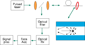
The optical fibre distributed temperature sensor is based on optical time-domain reflectometry (OTDR). In this technique a pulse of light is launched into the sensing optical fibre through a directional coupler, see Figure 1.

The light pulse is scattered as the pulse passes down the fibre due to various mechanisms. A proportion of the scattered light, referred to as backscatter, is returned back towards the source. The backscattered light is directed by the directional coupler in the OTDR and routed to a suitable highly sensitive receiver.
In a uniform optical fibre, the intensity of this returned light shows an exponential decay with time. Therefore, knowing the speed of light in optical fibre and knowing the time the light has taken to travel in the optical fibre the OTDR can calculate the distance to the various mechanisms in the optical fibre that cause the light to scatter.
Components of the backscatter signal
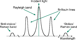
The OTDR technique is well established and used extensively in the optical telecommunications industry for qualification of an optical fibre link or fault location. In telecommunication OTDR units the 'Rayleigh' backscatter signature is examined. The signal is unshifted from the launch wavelength and is the one used by telecom engineers to verify the integrity of a fibre link. This signature gives information on loss, breaks and inhomogeneities along the length of the fibre. The Rayleigh signature is only slightly influenced by temperature differences along the length of the optical fibre.
Two other backscatter signatures 'Brillouin' and 'Raman' spectral lines are temperature sensitive. The wavelength of these lines are shifted from the launch wavelength and the intensity of the signals is much lower than that of the Rayleigh trace (see Figure 2).

The Brillouin spectral signals are close to the Rayleigh signal and are difficult to separate and measure. The Raman spectral signals are sufficiently strong and distinct to be used in temperature measurement.
The Raman signal comprises two elements - the 'stokes' and 'anti-stokes' lines that are shifted in wavelength from the Rayleigh signal in telecommunications grade optical fibre and can therefore be filtered from the dominant constituent of the total backscattered light. The longer wavelength stokes line is slightly influenced by temperature differences. The intensity of the backscattered light at the shorter anti-stokes wavelength is very sensitive to temperature variation along the length of the optical fibre and it is thus used for temperature measurement in the DTS system.
DTS systems configuration
A DTS system comprises one or more sensors of optical fibre cable, the optoelectronics unit with embedded processing software and a display unit. The DTS unit contains all necessary optics, electronics and data processing capability for interrogating the fibres and generating temperature profiles as well as other important information such as zone and alarm data. One unique laser source is used in the DTS systems, a Neodymium-doped laser at 1064 nm supplying pulses of <10 ns width (equivalent to <1 m length). A directional coupler separates the launch pulse from the backscatter signal and a fibre switch selects the sensing fibre to be interrogated.
The Raman backscatter signal is filtered and detected. This is then amplified and digitised by a high-speed analog-to-digital converter that samples the whole of the return signal at intervals programmable down to 2,5 ns. Digital averaging techniques improves the signal/noise ratio in a highly efficient manner prior to the data being sent to the display unit and/or other associated systems interfaces.
Measurement technique
The DTS system can make single and double-ended measurements of the sensing fibre. The doubled ended measurement is the method of probing the sensing fibre from each end. That is, a loop of fibre should be used and probed first from one end and then the laser source switched into the other end of the loop for a second measurement. The two signals are then processed.
Double-ended processing provides superior accuracy and speed of response in addition to a unique fibre break recovery system. Double-ended measurement has two major advantages over single-ended:
Accuracy - The effects of fibre loss are eliminated from the temperature measurement making the system insensitive to micro-bend and connector losses. Variations in loss along the length of the fibre can be caused by changes in strain on the fibre or by pressures on the fibre, giving rise to changes in local micro-bend losses. Both of these effects may change with time and if not detected could appear as errors in the temperature profile. Measuring from both ends and taking the geometric mean of the two signals eliminates this source of error.
Resilience - Temperature profile measurement can continue along the total length of the cable in the event of a break in the fibre. Since the fibre will continue to be probed from each end regardless, temperature information will continue to be available up to the break from each end thus maintaining the integrity of the system. In practice the DTS system may be set up to indicate the presence and position of the break and automatically switch to single-ended operation, to give uninterrupted sampling.
There are many other proven applications of DTS within the process, industrial and power areas. Some include: condition monitoring of the process vessel; pipeline leak detection; concrete curing; buried power cables monitoring; geothermal surveys and monitoring; dam leakage monitoring; induction furnace monitoring; spontaneous combustion.
DTS application example in South Africa
A leading South African petrochemical company uses 'Sensa' fibre-optic sensing technology (DTS) to detect the potentially dangerous hot spots in the most critical part of the process. In the design, a synthetic fuel process converts offshore gas into oil, which is then processed in a standard refinery. The most critical part of the process is known as methane reforming where gas is heated and then reacted with pure oxygen in a secondary reformer. A catalytic reaction thereafter creates syngas that is subsequently fed into a Fischer Tropsch process to produce oil.
Temperatures in this secondary reformer reach 1200°C. The shell is protected with refractory material but small defects, either material- or burner-related, can result in the creation of hot spots. These, if undetected, could lead to serious damage being caused to the vessel and eventually, shut down the process. For monitoring purposes, the reformer is divided into cone and barrel sections. Due to the proximity of the burner, the cone is particularly prone to developing hot spots.
The Sensa DTS uses optoelectronics to produce continually-updated temperature analyses along the entire length of the optical fibre, making it a cost-effective way to measure temperature over large surface areas or long distances where fixed point devices would be impractical. In addition, as fibre-optic cable is EMI-proof and because no electrical currents are used in data transmission, the Sensa DTS is particularly suitable for hazardous environments.
The stainless steel encapsulated sensor cables were laid around the three reformers and linked to a controlling DTS 0,5 km away. A complete temperature profile of all three reformers is continuously displayed and an alarm is set to sound immediately should temperatures at any stage reach a certain pre-set value. Certain decisions can then be made in regard to the reduction of loads, plant shutdown, or the cooling of the hot spot with air.
What is next for DTS?
To a large extent the future is limited only by the imagination to apply distributed temperature measurement to new applications.
For more information contact Hilton Preston, Spescom MeasureGraph, 011 266 1572, [email protected]

© Technews Publishing (Pty) Ltd | All Rights Reserved