


Most applications which incorporate a heating element require measurement of temperature. There are many different types of sensors available for temperature measurement, but obviously, the simplest approach is to use the heating element itself as the sensor.
This approach is especially suitable in applications where fitting a sensor is mechanically difficult, where the sensor for the required temperature range is expensive, or where the heating element is connected to the application by a cable and additional cabling to the sensor needs to be avoided.
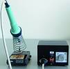
This article describes one of the possible approaches which is suitable for low-voltage heating elements. Measurement of temperature of heating element in a small handheld soldering pen will serve as an example application throughout the article.
Properties of the heating element
Heating elements designed for low voltages need to have relatively low resistance to deliver the required heating power. Since the delivered output power of the element should not change considerably over the operating temperature range, the temperature coefficient needs to be relatively small. However, it is usually high enough to use resistance of the element for determining its temperature. In our example application the 50 W heating element is operating at 24 V, has resistance of 12,3 Ω at room temperature and 13,0 Ω at 300°C.
Construction of cheap elements usually resembles wire-wound resistors: to pack long enough wire into a small space, the wire is wound into a coil which is mechanically supported by a piece of electrically non-conductive material. This means that the element has considerable inductance and the measurement technique needs to ensure that inductance of the element is distinguished from its resistance. This is important since the inductance may be influenced by surrounding objects and such interference would lead to incorrect results of the measurement.
Measurement set-up
To make sure that inductance of the heating element will not influence the results, the measurement needs to be performed at DC (zero frequency). Another usual requirement is to make sure that the measurement itself will not significantly increase the temperature, ie, the power dissipated in the heating element during the measurement needs to be kept low.
Where the heating element is connected by cabling (with or without connectors) it is also important to make sure that changes of resistance of the cable and connector contacts is compensated for. This is the case in our example application where the soldering pen is connected by both cable and connector and thermal coefficient of the heating element resistance is only 2,6 mΩ/°C.
This requirement is easily achieved in bridge configurations where we either make sure that the changing resistance we want to eliminate influences both branches of the bridge or that very similar resistance changes appear on both sides.
Configuration of the measurement bridge is shown in Figure 1. The bridge is powered by constant current source, which makes the bridge more sensitive to resistance changes and provides additional filtration of noise present on the 24 V power supply rail. Diode D1 protects the current source when the power P-channel MOSFET transistor is switched on (the heating element is powered). Diode D2 is of the same type and provides compensation of voltage drop across D1. It is necessary to place the two diodes close together to make sure both have the same temperature and hence the same voltage drop. Cabling and connectors are designated by double chevrons. It can be seen that the resistance changes in the ground lead does not influence the measurement results as it causes changes only in common mode voltage. The other two leads are assumed to have the same resistance and therefore changes of their resistance influences the two branches of the bridge in a very similar way and again do not imbalance the bridge. In this configuration the measurement is only possible when the heating element is not powered.
Changes in the extent of imbalance of the bridge correspond directly to changes of temperature of the heating element. These changes are observed by a differential amplifier (which needs to have internal protection against input overvoltage) and finally by A/D converter of a microcontroller which controls the whole application. Since the changes in heating element resistance are small, the bridge is always close to balanced state and the output voltage changes almost linearly with temperature (linear approximation is sufficient).
Real-world implementation of the measurement bridge is shown in Figure 2.
Practical results
In our example application (depicted in Figure 3) the bridge is connected to on-chip A/D converter of low cost 8-bit microcontroller MC68HC908QT2. The measurement range is from below room temperature up to over 500°C. Since the A/D converter has its resolution limited to 8 bits, the temperature resolution is approximately 2°C. The whole measurement chain provides very clean output voltage and the ADC output values are so stable, that attempts to increase resolution by oversampling and averaging would require introduction of artificial noise. The temperature regulation in this example application is accurate to ±2°C over the whole operating temperature range.
For more information contact Daniel Malik, Motorola, [email protected], or local Motorola distributors, Arrow Altech Distribution, 011 923 9600, Avnet Kopp, 011 809 6100 or EBV-Electrolink, 021 421 5350.
| Tel: | +27 11 923 9600 |
| Email: | [email protected] |
| www: | www.altronarrow.com |
| Articles: | More information and articles about Altron Arrow |
| Tel: | +27 11 236 1900 |
| Email: | [email protected] |
| www: | www.ebv.com |
| Articles: | More information and articles about EBV Electrolink |


© Technews Publishing (Pty) Ltd | All Rights Reserved
 printer friendly version