Power meters provide an early warning of thermal overload by monitoring the power consumption in 'high reliability' systems. Power monitoring is especially suitable for systems in which the load voltage and current are both variable such as industrial heating and motor controllers.
Such a power meter/controller (Figure 1) is based on the principle that power equals the product of current and voltage. Its typical accuracy is better than 1%.
Figure 1. This power meter, whose output voltage is proportional to load power, achieves ±1% accuracy
Method
A current sensor (U2) measures output current, and a four-quadrant analog voltage multiplier (U1 and U3) generates the product of output voltage and current. An optional unity-gain inverter (U4) inverts the inverted multiplier output. This power meter is most accurate for multiplier inputs (J1 and J2) between 3 V and 15 V.
Choose the current-sense resistor, RSENSE, as follows:
RSENSE (Ω) = 1/P (W)
where RSENSE is in Ω and P is the output power in W. If power delivery to the load is 10 W, for instance, choose RSENSE = 0,1 Ω.
The Figure 1 circuit, with a 0,1 Ω sense resistor, has a unity-gain transfer function in which the output voltage is proportional to load power. For instance, the output voltage is 10 V when the load power is 10 W. To change the gain transfer function, change the sense resistor as follows: Gain = 10 RSENSE.
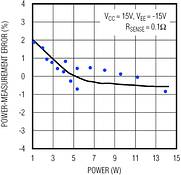
Figure 2 compares power-measurement error with load power for the Figure 1 circuit. Note that the accuracy is better than ±1% for load power in the 3 W to 14 W range.
Figure 2. The ‘Power-measurement error vs power’ graph shows measured power has better than ±1% accuracy for power levels between 3 and 14 W
Calibration
For proper operation, the analog multiplier must first be calibrated according to the following procedure (which also appears in Motorola's MC1495 data sheet). To calibrate the multiplier, remove jumper J1 (X input) and J2 (Y input), and use the following procedures:
(1) X-input offset adjustment: Connect a 1,0 kHz, 5 VP-P sinewave to the Y input, and connect the X input to ground. Using an oscilloscope to monitor the output, adjust RX for an AC null (zero amplitude) in the sinewave.
(2) Y-input offset adjustment: Connect a 1, 0 kHz, 5 VP-P sinewave to the X input, and connect the Y input to ground. Using an oscilloscope to monitor the output, adjust RY for AC null (zero amplitude) in the sinewave.
(3) Output offset adjustment: Connect both X and Y inputs to ground. Adjust ROUT until the output DC voltage is zero.
(4) Scale factor (Gain): Connect both X and Y inputs to 10 V d.c. Adjust RSCALE until the output voltage is 10 V d.c.
Digital isolators for I2C interfaces
Analogue, Mixed Signal, LSI
Würth Elektronik has expanded its range of digital isolators with 2-channel bidirectional isolators for I2C communication interfaces.
Read more...Powering smart sensor networks CST Electronics
Telecoms, Datacoms, Wireless, IoT
NeoCortec’s NeoMesh wireless mesh networking protocol and software stack is ideally suited for powering smart sensor networks where each device is required to send and receive small packets of data infrequently, but with high reliability.
Read more...Ultra-low-power smart metering EBV Electrolink
Analogue, Mixed Signal, LSI
ScioSense’s UFC23 sensor combines improved resolution and offset stability with ultra-low standby current, enabling high-end battery-powered water, heat, gas and leak detection meter designs.
Read more...Industrial vibration sensing simplified Altron Arrow
Analogue, Mixed Signal, LSI
The IIS3DWBG1 from STMicroelectronics is a high performance, three-axis digital vibration sensor engineered for demanding industrial applications where accurate motion monitoring is essential.
Read more...Understanding two key tools for cleaner serial data Altron Arrow
Editor's Choice Analogue, Mixed Signal, LSI
Understanding how pre-emphasis and equalisation works, and when to use one over the other, is critical when designing reliable high-speed systems.
Read more...Real-time monitoring for smart power distribution CST Electronics
Test & Measurement
By leveraging high-precision measurement, high-speed wave-recording, and AI-enabled analytics, the InHand Wireless Overhead-lines System empowers power utilities to accurately identify line faults and perform comprehensive load analysis.
Read more...Robust LoRaWAN for distributed IoT CST Electronics
Telecoms, Datacoms, Wireless, IoT
InHand Networks has unveiled its latest LoRaWAN gateway, the EC312, marking an evolution in industrial-grade connectivity solutions for distributed IoT environments.
Read more...5G mobile hotspot with integrated multimodal AI capabilities CST Electronics
Computer/Embedded Technology
MeiG Smart has launched its first 5G Mobile HotSpot solution, the SRT8710, a breakthrough in mobile connectivity that combines ultra-fast 5G communications with integrated multimodal artificial intelligence functions.
Read more...Smart IMU for high/low-g acceleration Altron Arrow
Analogue, Mixed Signal, LSI
The ISM6HG256X is a 6-axis intelligent inertial measurement unit that enables smart motion sensing, edge computing, and real-time awareness.
Read more...Compact Schottky diodes increase efficiency RS South Africa
Analogue, Mixed Signal, LSI
Gen 3 SiC Schottky diodes from Vishay in the compact SlimSMA HV package increase efficiency while enhancing electrical insulation.
While every effort has been made to ensure the accuracy of the information contained herein, the publisher and its agents cannot be held responsible for any errors contained, or any loss incurred as a result. Articles published do not necessarily reflect the views of the publishers. The editor reserves the right to alter or cut copy. Articles submitted are deemed to have been cleared for publication. Advertisements and company contact details are published as provided by the advertiser. Technews Publishing (Pty) Ltd cannot be held responsible for the accuracy or veracity of supplied material.


 printer friendly version