
Most microwave devices provide a number of specifications of varying importance. The significance of return loss, insertion loss, passive intermodulation product levels, and isolation will be considered in this article.
Manufacturers usually supply a large number of specifications for their products. Which specifications are important and what their significance is are not always clear.
This article will consider key specifications of a passive microwave device using a duplexer in a dualband cellular base-station as an example. Note that the values given are based on theoretical calculations and may differ from values measured on typical systems. However, the trends illustrated are indicative of what will be observed in practical systems.
System description
The function of a duplexer is to split or combine two frequency bands. This is done using two bandpass filters (Figure 1), so the 3 dB loss associated with couplers is avoided, and the isolation between the two frequency ports is very high.
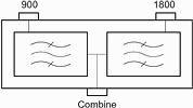
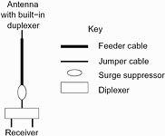
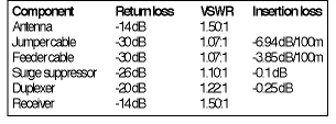
Grintek Antennas' duplexer is used to combine the 900 MHz and 1800 MHz (including UMTS) GSM bands. The specifications of the device make it well suited to this application. The system considered is shown in Figure 2 and the parameters of the various components are given in Table 1. The main objective of using duplexers in a base-station is to reduce the number of large, expensive feeder cables required in a system. This is achieved by using a duplexer to combine two frequency bands in the shelter and a dual-band antenna with a built-in duplexer to split the bands at the top of the mast. Flexible jumper cables of 2 m are used to connect the major system components.
Return loss (VSWR)
Return loss (or equivalently VSWR) is a measure of how well a device is matched. High return loss/VSWR means that a system is poorly matched, leading to a number of problems. A poorly matched system means that a significant portion of the power fed into the system is reflected and does not reach the load. A poor match also leads to standing waves in cables and other devices causing very high field intensities at certain points in the system. These high field intensities can lead to reduced power handling and increased intermodulation products (considered later).
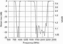
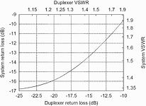
A plot of the return loss of a duplexer produced by Grintek Antennas is shown in Figure 3 and is seen to be well within the -20 dB (1,22:1 VSWR) specification over both bands. The effect of varying the duplexer return loss on the return loss of the system shown in Figure 2 is shown in Figure 4. It is clear that increasing the duplexer return loss above -20 dB has an increasingly detrimental effect on the system return loss.
Insertion loss
The insertion loss of a device is an indication of how lossy a device is. Higher loss is detrimental because it reduces the amount of power reaching the load and increases noise figure. Even relatively small losses can have a large effect on system performance. For example, 0,5 dB loss will reduce a 20 W transmitter to less than 18 W, and increase the system's noise figure by 0,5 dB. In cellular applications this change will reduce the area of a cell by roughly 7% (based on the Hata model in GSM 03.30).
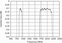
The measured insertion loss of a duplexer from Grintek Antennas is plotted in Figure 5. The insertion loss is well below the specification of -0,25 dB over both bands.
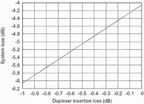
The system insertion loss as a function of the duplexer insertion loss for the system in Figure 2 is plotted in Figure 6. Significantly, a 0,1 dB change in duplexer loss produces roughly a 0,2 dB change in system insertion loss. This amplification effect should be borne in mind when considering the insertion loss of a device.
Intermodulation products
Intermodulation products are caused when more than one signal is fed into a nonlinear device. This effect is especially prevalent in active devices such as amplifiers that display a saturation effect, but passive devices display a similar effect albeit at lower levels.
Odd order intermodulation product frequencies are very close to the carriers that generate them. These signals often fall into the receiver band and can cause ghost signals that interfere with genuine signals.
Intermodulation products are generated in passive devices at the junction between two dissimilar materials and due to material effects. The level of these passive intermodulation products is very low, but not negligible.
For example, the GSM specification requires that a base-station receiver must have a sensitivity of better than -104 dBm, so Grintek Antennas tests each device to ensure that third order passive intermodulation products are below -107 dBm with two 20 W (43 dBm) carriers. Even these extremely low intermodulation product levels (150 dB below the carriers) are not far below the sensitivity of the receiver.
Isolation
Isolation is a measure of how well ports on a device that are not supposed to be connected are isolated from each other. The main effect of inadequate isolation is to reduce the sensitivity of receivers.
Low isolation means that significant interfering signal levels leak into receivers that should be isolated from those signals. This can lead to desensitisation of the receiver because the interfering signals are 'noise' to the receiver. In extreme cases the receiver can be driven into its nonlinear region and can generate intermodulation products and cross products causing further desensitisation.
Grintek Antennas specifies an isolation of at least 70 dB. In light of the above discussion on intermodulation products, this would seem to be vastly inadequate, but the receiver also includes filtering that suppresses out-of-band signals. The combination of duplexer isolation and receiver filtering will thus be adequate as long as the duplexer isolation is high.
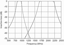
The duplexer produced by Grintek Antennas also acts as a pair of bandpass filters that help to reduce spurious signals as shown in Figure 7.
Conclusion
The key passive microwave specifications of return loss (VSWR), insertion loss, intermodulation product levels, and isolation are considered. The significance of each of these specifications and their effect on a system are discussed using the example of a duplexer in a dual-band cellular base-station.
For more information contact Grintek Telecom, 012 672 8216, [email protected]

© Technews Publishing (Pty) Ltd | All Rights Reserved