


RFC documents are a series of technical and organisational notes for Internet-related protocols and procedures. Some RFCs represent true Internet Standards, while others are categorised as informational (such as RFC 2544) or even experimental (see www.rfceditor.org or www.faqs.org/rfcs/</a>).
RFC 2544 discusses and defines a number of tests that may be used to describe the performance characteristics of a network interconnecting device. RFC 2544 provides a standard methodology for all equipment vendors to use, allowing customers a clear, 'apples-to-apples' comparison of devices. The tests described would be used in the development, manufacturing, and installation of the network devices.
As Ethernet testing moved from manufacturers to service providers, RFC 2544 became a natural testing methodology to use. Unlike traditional TDM- and ATM-based services, Ethernet does not have stringent requirements for quality based upon class of service. The testing requirements for MANs (metropolitan area networks) have traditionally focused on throughput, latency, and frame loss rate rather than bit error rate and 'five nines' reliability. Thus, RFC 2544 takes the place of quality of service testing seen in traditional networks.
The RFC 2544 methodology is centred on six out-of-service tests, run automatically at various frame sizes. As an intrusive test, it cannot be performed in a monitoring mode (on a live network).
Test scenarios
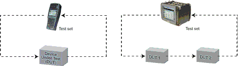
The configuration of Figure 1, 'Single tester, single device' is typical for benchmarking a network device upon acceptance or installation. A single test set sends traffic to one port of the device and measures the output of another port. A single test set can characterise multiple devices in serial: 'Single Tester, Multiple Devices' in Figure 1.
For installed networks, the configuration 'Two testers, single device or network' in Figure 2, is the most realistic. The sending and receiving end may be separated by distances that make using a single tester impractical. The most straightforward manner of coordinating the two ends for testing is in setting one unit to loop mode. Unlike looping a traditional TDM-based network (PDH/ T-Carrier, SDH/SONET), a simple 'hard loopback' will not suffice. The Ethernet frames and IP packets must have the proper source and destination addresses to return to the original tester. While in loopback mode, the loop unit swaps the source and destination addresses for both the Ethernet and IP header (if applicable).
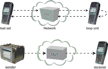
The operator at the far end can set the loopback mode manually or the loop unit can be placed in a responder mode, whereby it only loops after being sent a command from the other test unit. At the conclusion of the test, the loop can also be brought down remotely.
Frame structure
Test layers: RFC 2544 is designed for layer 2 and layer 3 devices. As such, each test frame must have a valid MAC header, preamble, and inter-packet gap. For testing layer 3 devices, such as routers, a valid IP header is also required. Though VLAN support is not mentioned, VLAN is an important element of Ethernet and should be included as appropriate. Unframed testing, where the payload data is not encapsulated into a valid Ethernet frame, is not compatible with RFC 2544 device testing.
RFC 2544 recommends using a UDP Echo Request packet because a router may drop data if the proper session initialisation sequence has not been established or if the payload is an unrecognised protocol. These concerns do not apply to layer 2 devices and for testing Ethernet networks, any test payload is acceptable. Sunrise Telecom uses a frame payload that consists of a sequence number, a timestamp, and a test pattern specified by the user. The sequence number and timestamp are used to accurately measure lost frames and latency, respectively.
Frame sizes: The standard sizes for Ethernet testing are 64, 128, 256, 512, 1024, 1280, and 1518 bytes. For systems that support jumbo frames, such as 4096- or 9000-byte frames, these frame sizes should be tested as well. With the exception of the reset test, each of the tests is run separately for each specified frame size.
The benchmarking tests
RFC 2544 defines six standardised tests: throughput; latency; frame loss rate; back-to-back frames; system recovery; reset.
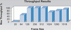
Throughput: the throughput test determines the maximum frame rate without lost frames the DUT can manage. The test begins at 100% frame rate by sending a pre-determined number of frames. If any frames are lost, the test is repeated at a lower frame rate. This process continues until the maximum throughput is determined.
Sunrise Telecom uses a binary search algorithm for determining the throughput. The standard test method reduces the throughput by a set increment, such as 10%. This is not the most efficient algorithm available especially for determining the throughput with a better resolution, such as 1%. The binary search changes the throughput value by ever decreasing steps: 50, 25, 12,5, 6,25, 3,125%, etc. The throughput is increased or decreased depending on the results of the previous test. The algorithm continues to run until the throughput is determined to within the specified resolution, typically 1 to 10%. Once the maximum throughput is determined for each size, the results are displayed in a chart (Figure 3).
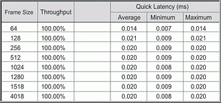
Latency: The standard latency test is to run traffic at the predetermined throughput rate for two minutes and measure the latency of a single tagged frame sent at least one minute into test. The reported latency is the average of 20 such tests.
Strict adherence to the standard would require 280 minutes - over 4 hours - to complete for all frame sizes. Sunrise Telecom has devised a 'quick latency' test that eliminates the need to run a separate and time-consuming latency test. During the throughput test, the latency of the test frames is measured and averaged. Results from failed throughput tests are discarded. The latency results from the highest successful throughput test are kept and reported. Latency results as a function of frame size and throughput are tabularised (Figure 4).
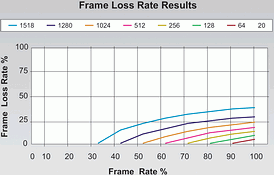
Frame loss rate: The frame loss rate test plots the frame loss as a function of utilisation. Similar to the throughput test, the test begins at 100% frame rate by sending a pre-determined number of frames and recording the percentage of lost frames. The bandwidth is reduced by a pre-set amount, 10% or less, and the test is repeated. If two successive trials result in no frame loss, the lower rates are not tested and assumed to have zero frame loss. This test is repeated for each frame size.
The results are plotted on a graph of percentage of lost frames as a function of frame rate. Different frame sizes are plotted on the same graph using different colours (Figure 5). Sunrise Telecom also provides a table so that the results can be easily exported to a spreadsheet or other program.
Back-to-back frames: The back-to-back frames test determines the maximum number of frames sent back-to-back with minimal IPG (in other words, at 100% frame rate) that the DUT can process without losing frames. The test begins with a specified number of frames and repeats with more or fewer frames until it determines the maximum number. As always, this is repeated for each frame size. This test may go by other names, such as 'burstability' or 'maximum throughput' test. The results are provided in tabular format.
System recovery: The system recovery speed is the time the DUT takes to stop losing frames when the frame rate is reduced from a stressed to a normal state. The device is stressed for at least one minute with too much traffic, typically 110% the rate determined by the throughput test, such that it loses frames. Then, the traffic is reduced to 50% of the pre-determined throughput. The time between the drop in frame rate to the last lost frame is averaged over several test runs for each frame size.
Reset: The reset test measures the time it takes for the DUT to begin forwarding frames after a hardware or software reset or a power interruption. Unlike the other RFC 2544 tests, only the smallest frame size, typically 64 bytes, needs to be tested. The delay between the last frame forwarded before the reset and the first frame after the reset is the reported reset speed. The test should be run for each type of reset.
For more information contact Chris Nel, Lambda Test Equipment, 012 349 1341.
| Tel: | +27 12 349 1341 |
| Email: | [email protected], [email protected] |
| www: | www.lambdatest.co.za |
| Articles: | More information and articles about Lambda Test |


© Technews Publishing (Pty) Ltd | All Rights Reserved
 printer friendly version