


Ref: z2717155m
Manufacturers of test and measurement equipment have long recognised the need to enable automated test and therefore build equipment with some type of I/O interface. GPIB (General Purpose Interface Bus) and RS232 are two of the more common I/O interfaces. However, with computers now supporting high speed Universal Serial Bus (USB) 2.0, manufacturers should consider USB as an alternative or additional I/O to the ageing GPIB and RS232. In manufacturing test applications, USB's high data rate of 480 Mbit/s will decrease test times. In an R&D environment, USB's ease of use will enable engineers to quickly construct a test system and characterise a design over frequency or temperature. This article will provide an overview of the benefits of USB in automated test, how USB might be used to communicate to test and measurement equipment, and some USB design guidelines.
To understand the benefits of using USB for automated test, consider how an automated test application is created. There are two main tasks:
* Making the physical connection between the computer and the test equipment.
* Developing the test application software that executes on the computer.
For both tasks, the use of GPIB, RS232, and USB will be explored and contrasted.
Making the physical connection
To set up an automated test using GPIB, a GPIB host bus adapter card and GPIB software drivers must be located and installed in the computer. This is because GPIB is not built into any standard PC. Fortunately, there are many manufacturers of GPIB cards. Unfortunately, they are expensive and not found at the nearest store. This is also true for GPIB cables. After a GPIB host bus adapter card has been purchased and installed, and the necessary GPIB cables are in-hand, the cables must be connected from the computer to the test equipment. The GPIB cables are thick, containing 24 wires, and are sometimes difficult to fit and manoeuvre into tight spaces. After the cables are connected, GPIB addresses for the equipment must be manually configured. The GPIB addresses chosen must be unique and must not conflict with the address of the GPIB card in the computer. There is a maximum of 15 devices in any GPIB topology and typical data rates achieved are ~750 KBps.
To set up an automated test using RS232, the proper RS232 cables must be located. RS232 cables are usually easier to locate than GPIB cables, but there are many different types. If an RS232 test system is not working, the first thing many try is a different cable. If a new cable is not successful, many try to change RS232 parameters like baud rate, parity, start/stop bits, flow control, etc. There are too many variables and this leads to frustration. The good news is that RS232 is built into computers, so no host bus adapter installation is needed. However, the number of available RS232 ports is limited to two, and since RS232 is strictly point-to-point (no ability to daisy-chain from device-to-device), two RS232 ports means only two devices can be connected. If more than two RS232 ports are needed, multiport RS232 host bus adapters must be used. Typical data rates with RS232 are much slower than GPIB due to baud rate limitations.
Compared to GPIB and RS232, making the physical connection at the computer end with USB is easy. Computers have been shipped with USB hardware for many years (163 million in 2000, 153 million in 2001, and 173 million in 2002) and the 'universal' in the USB name is certainly appropriate. Most USB equipped computers offer at least two USB ports. In the near future, this will grow due to Intel's 845G chip set, which supports six high-speed 480 Mbps ports. Each USB port on a computer acts as a 'root port' and supports a topology (if additional external hubs are used) of up to 127 devices. This is much better than the limitation of two devices for RS232 and 15 devices for GPIB. USB should enable new kinds of test systems, with many more instruments connecting into a single computer. USB hubs are readily available and do not introduce significant delays.
With USB, making the physical connection to the test equipment is also easy - whether the test equipment has a USB interface or not. If the test equipment does not have a USB interface, USB can still be used, but a converter is required. For a GPIB interface, several companies now provide USB-to-GPIB converters. These typically contain a general purpose USB chip, firmware, and GPIB hardware and convert a protocol on the USB side into the necessary signalling on the GPIB. See Figure 1.
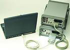
The benefit is that an expensive GPIB host bus adapter card no longer needs to be installed to communicate with the GPIB test equipment. Applications written for GPIB do not even have to change, since the USB-to-GPIB converter can be made to appear as a GPIB host bus adapter card. These converters also eliminate a GPIB cable, since they can be plugged directly into the GPIB interface on the test equipment. Using such a converter may be the only solution if there are no expansion slots available on the computer.
Another advantage to a USB-to-GPIB converter is that if several engineers have an occasional need to run an automated test, it is much easier to share a USB-to-GPIB converter with others than it is to share a GPIB card. When transferring large transfers of data, the performance of even 12 Mbps full-speed USB-to-GPIB converters is sufficient to match the 25-year-old GPIB's performance. However, if the test application has a critical need to perform many short transfers, such as writing to an electronic switch, the performance of USB-to-GPIB converters may affect the overall test time. To optimise short transfer performance, connect the USB-to-GPIB converter to a high-speed USB port.
If the test equipment has an RS232 interface, USB-to-RS232 converters are also available from several manufacturers. They appear to the operating system as extra COM ports.
If the test equipment has a USB interface, all that is needed is to connect a USB cable (cheap and readily available) from a USB port on the computer to the test equipment. Since USB is plug-and-play, there are no concerns about setting up unique addresses. The address is assigned by the operating system.
After making all of the USB connections and before turning everything on, software should be installed on the computer. This is true for any USB device that is not natively supported by the operating system (OS). This is because, as stated above, USB is plug-and-play and the OS will automatically detect when a new device is added to the topology. The OS enumerates the newly attached device, reading the device descriptor, configuration descriptor, interface descriptor, and endpoint descriptors. The OS then attempts to find the most suitable driver. If software has not been installed, a suitable driver will not be found and the operating system will give up, and tell you. At this point, some users may not know what to do. It is best to install software first. For test and measurement equipment, this means installing I/O library software. Installing I/O library software will install files that enable the operating system to associate the correct driver with the USB device. Installing I/O libraries also make it possible to write test applications that communicate over USB.
Developing the test application
A test application is typically developed using I/O library software implementing the VISA (Virtual Instrument Software Architecture) standard. VISA already supports the GPIB, RS232, and other interfaces. T&M companies are currently working to add VISA support for USB. This effort builds on the effort of another group working within the USB Implementers Forum (USB-IF) Device Working Group (DWG) to create a USB test and measurement class specification. Developing a new USB device class specification was necessary because of the unique needs for test and measurement devices. One need was to map out-of-band GPIB messages such as clear, trigger, srq, and remote/local to USB. Another need was to define how interrupts get communicated from the device to the computer.
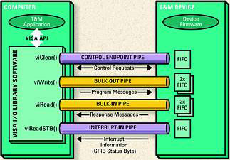
The USB test and measurement class (USBTMC) specification defines what USB endpoints are needed on a device and defines how program messages are sent and how response messages are read. See www.usb.org for the most current information. The goal for the USBTMC specification was to address the communication requirements of a broad range of test and measurement devices, from simple sensors to mainframes with multiple measurement functions. The goal for the USB488 subclass specification was to address the need to move the GPIB communication model to the USB. Figure 2 shows the communication paths (USB pipes) between a host computer and a USB488 implementation.
The group working on the next version of the VISA standard will define syntax for obtaining a handle to a USB test and measurement device (using the VISA viOpen() API) and will define specific attributes for USB devices. Once a handle is obtained, then VISA applications can write to the device and read from the device the same as for any other VISA supported interface. To change an application from using a voltmeter with a GPIB interface to instead use a voltmeter with a USB interface will require only changing the viOpen() syntax and a recompile.
The USB-IF DWG and VISA standards efforts are needed so that I/O library software can support USB test equipment from multiple vendors, just as one I/O library can support GPIB and RS232 test equipment from multiple vendors in the same test system.
USB design for test and measurement equipment
To begin to design USB into test and measurement equipment, the following questions immediately arise:
* Should the design be low-speed (1,5 Mbps), full-speed (12 Mbps) or high-speed (480 Mbps)?
* What other key factors should be considered when choosing USB device silicon?
The speed should be full-speed or high-speed, and not low-speed. According to the USB 2.0 specification - 'the low-speed mode is defined to support a limited number of low-bandwidth devices, such as mice, because more general use would degrade bus utilisation.'
Full-speed may seem like an obvious choice, given that most computers today support full-speed and not high-speed. But keep in mind that USB 2.0 is designed to be fully backward compatible with USB 1.1. USB 2.0 supports low-speed, full-speed, and high-speed communications. This means a high-speed device will work when connected to a USB 1.1 full-speed only computer (it will just operate at full-speed rather than high-speed) and a high-speed capable USB 2.0 computer will communicate at full-speed to a full-speed device. Also keep in mind that high-speed USB 2.0 support on PCs should grow rapidly. It is also easy to upgrade an existing computer with high-speed USB 2.0 by purchasing a USB 2.0 host bus adapter card. The choice of full-speed or high-speed should not be based on compatibility, but rather on the data rates required by applications.
For large transfers, full-speed implementations realistically provide about a 1 MBps transfer rate. High-speed implementations will provide anywhere from 6 MBps to 40 MBps, depending on the architecture and firmware of the device and the USB software on the computer. It is true that data will burst at 480 Mbps (60 MBps), but sustained data rates are lower due to USB overhead, computer software overhead, and device overhead.
After choosing full-speed or high-speed, the choice of USB device silicon still depends on several other criteria:
* Device class. Some USB silicon is built for specific device classes. For example, a USB chip may be targeted to mass storage devices and therefore is optimised for the mass storage device class. Other USB chips are general purpose and firmware can determine the device class that gets reported to the operating system when the device is enumerated. To implement the test and measurement class (USBTMC) specification, use a general purpose chip. Whatever device class is to be implemented, the class specification should be consulted to understand any extra requirements or opportunities for optimisation.
* Number of endpoints. Most general purpose USB chips provide the required control endpoint and two or more configurable endpoints. The endpoints are configured by firmware to be bulk, interrupt, or isochronous. USBTMC requires three endpoints (control, bulk-OUT, bulk-IN). A fourth endpoint (interrupt-IN) is required if the device is to communicate interrupt conditions (similar to GPIB service requests) when measurement results are ready or when an error occurs. Most USB silicon will support at least this number of endpoints.
* Amount of endpoint FIFO memory. When the computer sends data to the device, the data is stored in Bulk-OUT endpoint FIFO memory until read by device firmware. When the computer reads data from a device, the data is read from Bulk-IN endpoint FIFO memory. Some USB chips offer more FIFO memory than other USB chips and will result in more efficient data flow.
* Endpoint FIFO memory access method. Some USB silicon will provide both programmed I/O and DMA memory access methods. DMA relieves the device processor from moving all of the bytes so the processor can do other work. The most efficient designs will DMA multiple bytes at a time.
* On-the-go (OTG) support. The new OTG USB specification allows a device to temporarily act as a USB host. This is a great idea for many applications, such as a USB digital camera sending pictures directly to a USB printer. Test and measurement equipment frequently produce images, and it would be nice to send them directly to a printer. However, OTG silicon and the needed OTG software infrastructure need to mature in the consumer market before adopting OTG in test and measurement equipment, which frequently must be supported for a long time.
Another design decision involves how users will connect the device. A USB device can be designed to use a captive cable, a standard-B plug, a mini-B plug, or an alternative plug. The plugs are shown in Figure 3, along with a GPIB cable for comparison.
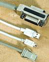
A captive cable design means the cable is an integral part of the device. This is how USB mice and keyboards are designed. The free and unattached end of the cable has a standard-A connector and is plugged directly into the computer USB port. A disadvantage of a captive cable design is that an assumption must be made as to what the optimal cable length should be.
Many devices use the original standard-B plug. The advantage to standard-B is that most cables in use today use standard-B. The disadvantage is size.
The mini-B connector and plug were created to meet the needs of small portable devices. The mini-B has a much smaller footprint. The other advantage of mini-B is that it is specified to last through 5000 insert/remove cycles, while the standard-B is specified at 1500.
The last option to consider is to use an alternative plug. This makes sense if the USB device will be used in a harsh environment and must withstand vibration and shock, or if it is important to prevent accidental disconnect of the device. Any device with an alternate plug should be shipped with a suitable cable.
Since USB provides power on the bus, a choice must be made whether a product will be self-powered or bus-powered. Of course there is a limited amount of power available, so typically only smaller, portable, less complex test equipment could be bus-powered.
Finally, every device must have a 16-bit vendor identification and 16-bit product identification. The USB-IF currently supports two options for getting the vendor identification. The product identification values are managed by the vendor.
Conclusion
Providing USB as an additional or alternative I/O on test and measurement equipment will provide test engineers an easier and faster path to measurement results. USB is easier to use because it is pervasive and cables, hubs, and converters are readily available. USB is faster than other interfaces thanks to the 480 Mbps high-speed supported in USB 2.0, which is ready now.
Most computer users have now gone through the experience of connecting a USB peripheral of some kind. The experience with test and measurement equipment should not be any different.
| Tel: | +27 12 678 9200 |
| Email: | [email protected] |
| www: | www.concilium.co.za |
| Articles: | More information and articles about Concilium Technologies |


© Technews Publishing (Pty) Ltd | All Rights Reserved
 printer friendly version