


As system designs begin to use components at the 130 and 90 nm process nodes, power consumption has once again hit the headlines.
At 130 nm geometries, static power (caused by current leakage) has become an issue: at 90 nm, it looks like being the predominant effect determining the power requirements of a semiconductor device.
The move toward low-power architectures throughout the 1990s, largely fuelled by the increase in use of mobile and portable equipment of all types, was enabled in no small part by the progress in silicon geometries - each shrink more or less guaranteed savings in power consumption and increases in clock speed. But now it seems likely that this trend has gone into reverse, and that in the future designers will once again need to look very carefully at power budgets from a systems point of view.
In parallel with the move toward low-power and battery powered systems has come a drive to reduce time-to-market: meanwhile, economic conditions over the last three to four years have led companies to look closely at all of their costs - including ASIC NRE costs. The net result has been an increasing trend away from ASIC designs and toward FPGAs.
Power considerations
So how does the increased use of FPGAs square with the need to reduce system power? In fact, FPGAs have their own unique power consumption characteristics. Designers, whether working with 130 and 90 nm-based chips or not, need to understand these fully as they specify devices, and as they undertake the design of the overall system. In particular, designers are often surprised at the differences between the behaviour of FPGAs and ASICs, when it comes to power.
There are four basic components that need to be examined when designing a system that includes FPGAs (and, indeed, when evaluating power consumption when considering which FPGA technology to use). They are static power; dynamic power; power-up or in-rush power; and configuration power (Figure 1). The power requirements for the complete system need to account for all four of these components.
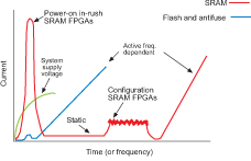
Static and dynamic power consumption are familiar concepts: and here, the FPGA behaves in a similar fashion to an ASIC - although actual power consumption depends on the technology chosen. The static power is the minimum power required to keep the device 'powered-up' with the clock inputs not switching and the I/Os drawing minimal power. Some FPGAs offer a feature that disables the I/Os and puts the device into a 'sleep' mode to further reduce the static power draw.
Of the three main FPGA types, antifuse-based FPGAs consume less static power than flash-based devices, which in turn consume significantly less power than SRAM types. This is due as much to architectural as technology features. SRAM FPGAs use a six transistor SRAM cell to interconnect the routing lines and logic cells. Although the static RAM cell consumes low power, the pass transistor is active, leading to the higher static power requirement.
Dynamic power is the power consumed while the clock is active and the logic elements are switching. Dynamic power will vary, sometimes dramatically, depending on the clock speed, the particular design being implemented and the I/O activity. But the choice of FPGA technology also has a significant impact. Antifuse technology exhibits the lowest dynamic power consumption, while SRAM-type FPGAs exhibit the highest - a fact that can often rule out their use in power-sensitive and battery-operated applications. Flash-based technology falls somewhere between antifuse and SRAM types.
Dynamic power consumption (and performance) is very sensitive to switched capacitances, mainly routing capacitances. Both flash and antifuse FPGAs have low synchronised capacitance, leading to lower power consumption.
Once again, the higher dynamic power of the volatile SRAM-based devices is due to the combination of the FPGA architecture and the SRAM technology. These factors also cause increased frequency to produce significantly more power consumption than is the case for either flash or antifuse FPGAs.
Antifuse FPGAs offer significantly lower dynamic power than either SRAM or flash FPGAs. This is directly related to the low switching capacitance and resistance of the antifuse element. The antifuse FPGA dynamic power consumption increases with frequency at a much lower rate than the other technologies for the same reasons. Choosing an antifuse-based device can reduce dynamic power consumption by up to a factor of five when compared to the equivalent SRAM-based solution.
In flash and antifuse-based devices, the power performance is more or less completely described by the static and dynamic power consumption parameters. Designers using SRAM-based designs, however, need to consider two other elements in the device specification: in-rush power and configuration power. It is here that SRAM-based FPGAs differ so markedly from the ASICs that they often replace.
In-rush (or power-up) power is consumed when the FPGA is initiated. In fact, there are some power-up current requirements inherent in all 'system' type FPGAs. These are due to the power-up requirements of on-chip memory and advanced I/O features. This component of transient power-up current is independent of the technology and is directly related to the additional system features that have been added.
Power-up
However, since SRAM FPGAs are volatile devices, they need to be re-initialised each time power is cycled. Since the logic is in an indeterminate state, this results in an exaggerated spike in current demand (see Figure 2). This in-rush can be as high as 2 A in some FPGA technologies and can last for several microseconds. Such a short-term spike can greatly reduce battery life in portable applications: in many cases, the designer will need to size the system power supply specifically to deliver the surge of current needed during the initial power-up sequence.
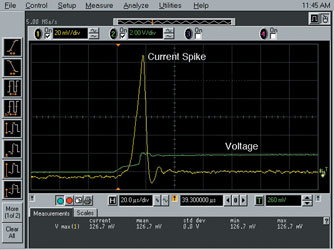
Neglecting this requirement can lead to 'mysterious' brown-outs and other power supply and PCB initialisation issues. Although many FPGA users are surprised by the power consumed during the power-on process, this current spike phenomenon (Iccpo) is actually well-documented in the various SRAM FPGA vendors' datasheets.
SRAM technologies exhibit similar power-up sequencing issues, regardless of how they are initialised. The reason is that the device configuration SRAM is in a non-deterministic state on power-up. Tristates are therefore not properly enabled, there are bus contention issues, and pull-ups and pull-downs can be simultaneously active. The net result is a significant spike in the power rail.
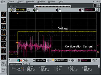
Configuration power is dissipated when an SRAM FPGA is being loaded with its configuration data. Again this is due to the fact that SRAM FPGAs are volatile devices, which need to be (Figure 3). From a power budget point of view, the designer must also remember that during the configuration phase the system needs to provide power for whatever nonvolatile device is used to provide the configuration data - typically one or more EEPROMs. In some systems a microprocessor may be used to boot up the system using existing nonvolatile memory, eliminating the dedicated 'boot PROM'. This can reduce power consumption, but only at the expense of cost, since the system memory has to be increased to hold the SRAM configuration data.
Most systems require a portion of the design to be live at power-up to talk with the bus and power-up the rest of the system. Typically, an FPGA is used as the system controller. However, if an SRAM device is used as the system controller, then an additional component is required to provide the boot-up capability. Typically, a small CPLD is used to perform this function, which again will add to the total system power requirement.
Choice
Choosing the right FPGA is a complex decision. A designer needs to carefully evaluate density, nonvolatility, reprogrammability, performance, security and power consumption to make the best choice for a specific application. FPGA technologies differ widely in their power consumption characteristics, and as the focus falls once again on this issue, it seems likely that power may become the deciding factor in many future designs.
| Tel: | +27 11 315 8316 |
| Email: | [email protected] |
| www: | www.asic.co.za |
| Articles: | More information and articles about ASIC Design Services |


© Technews Publishing (Pty) Ltd | All Rights Reserved
 printer friendly version