


In recent years, compliance to EN61000-3-2 has been required in order to do business within the European Economic Community. AC-DC power supplies were classified as 'Class D' products under this standard. This class of products has harmonic current limits that vary in direct proportion to the amount of power drawn from the AC line. In order to attenuate the harmonic currents sufficiently to meet the varying limits of this standard, a technique called 'Active power factor correction (PFC)' has been universally used. This technique results in an off-line switch-mode power supply with a near unity power factor and with very low harmonic currents. Active PFC circuits can be complex and, because they are active, they can generate considerable EMI and require extensive filtering.
The recent amendment to EN61000-3-2 has restated the harmonic current limits required for compliance as applied to most professional and industrial equipment that consumes less than 1000 W. In many cases, the limits of Amendment 14 can be met without using active power factor correction. Alternatives, such as passive harmonic attenuation, are now an attractive substitute, especially given the inherent cost, reliability, and noise advantages of passive solutions.
As shown in Figure 1, the approach here is to address the requirement with a conventional front-end and passive harmonic filter. The system consists of a passive harmonic current attenuation module - labelled MiniHAM - and an auto-ranging AC-DC front-end module - labelled FARM4. Combined with hold-up components, the system provides full compliance to EN harmonic current, EMI, and transient immunity standards.
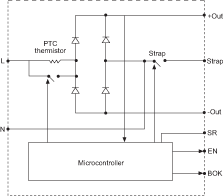
The holdup capacitors collect and store energy at the peaks of the line voltage. Energy that is stored in the capacitors is continuously delivered to the downstream load. It is convenient to incorporate harmonic filtering on the AC line; however, in the interest of minimising power losses, there is an advantage to incorporating the filter after the rectifier. Typically, with a conventional front-end required to operate over the entire universal input voltage range of 85 to 264 V a.c., the rectifier bridge incorporates a feature known as doubling or strapping. In this case, the doubler is engaged automatically over the input voltage range of 90-132 V a.c., and disengaged in the range above 180 V a.c. so as to reduce the range of DC voltage on the bus by a factor of two.
Figure 2 is a functional diagram of an autoranging rectifier. The DC bus voltage in the low range (90-132 V a.c.) is 2v2 Vrms, or approximately the peak voltage of the AC line. In the upper range, the bus voltage is v2 Vrms. The result is that the DC output bus is approximately 320 V d.c. at either 115 or 230 V a.c., thus reducing the required operating range of the downstream converters, which in turn affords a power density and efficiency advantage. In the bridge mode or high range, where the switch labelled 'strap' is open, the series capacitors may be treated as a single capacitor of half the individual value. In the doubler mode (switch closed), the capacitors are each charged individually on alternate half line cycles.
The harmonic filter module includes two mutually coupled inductors in series with each side of the applied voltage. The slope of the power derating and dissipation curves is reduced by a factor of two in the post rectifier application when operating in the low range, or doubler mode. This is because only one of the two coupled inductors is conducting load current during any half cycle, whereas both would be conducting each half cycle when employed on the AC line in front of the rectifier bridge.
The point here, is that when the AC front-end of the power conversion system (Figure 1) is in the doubling mode, there is a distinct advantage to having the harmonic filter on the DC side of the rectifier. This is because power dissipated, or loss in the filter is reduced by a factor of two in the low range. So there is an incentive to use the harmonic attenuator on the DC side of the bridge. Basically, it has a positive impact on the amount of power derating as the line voltage is decreased. In this case, the harmonic filter is specified to have a maximum power rating of 600 W, ie, at both 115 and 230 V a.c., whereas on the AC side of the bridge, the power would have to be derated to 300 W.
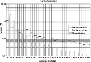
Figure 3 illustrates actual harmonic current data relative to the imposed limits at full rated power using the hardware solution described here.
Conducted emissions standards such as EN55011 and EN55022, set quasi-peak and average limits on the spectral contents of conducted noise reflected from the input of power systems back to the source. In order to comply, all of the conducted noise - the peaks in the spectrum - must fall below the specified limits.
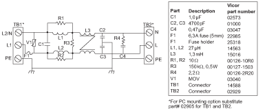
Most switching power supplies today operate at a frequency between 100 kHz and 1 MHz. Usually, the dominant peaks in the conducted noise spectrum reflected back to the power line correspond to the fundamental switching frequency and its harmonics. Typical filters, such as shown in Figure 4 (and included in the FARM4 of Figure 1), attenuate the amount of reflected noise and use both common and differential mode filtering. Common-mode noise is, by definition, the noise component that is common to both power lines, and is equal in both phase and magnitude on each of the input lines. The 'protective' earth connection provides a return path. The differential component on the other hand is equal and opposite in phase in each leg of the line.
The Transient Surge Immunity requirements as defined in EN61000-4-5, Level 3, specify that the power conversion systems equipment must withstand a 1000 V pulse superimposed on the mains. The pulse rise time is 1,2 μs with a tail that is 50 μs. Riding on top of the line voltage, this surge can occur at any phase angle with either polarity. The equipment has to be able to withstand this event without failure in order to comply with this standard. The standard requires that the applied transient voltage be set to 1000 V, line to neutral and 2000 V, line or neutral to earth (or chassis), during the test.
The simplest way to deal with this transient surge requirement is to provide transient protection right up front (again referring to the circuit diagram of Figure 1) in the form of a metal oxide varistor, which clamps the applied voltage to a safe and non-catastrophic level. The transient suppressor goes into conduction at the specified threshold and dissipates some of the energy associated with the transient event. Ultimately - and this is a good design practice - the system should be designed such that the bulk of the energy is absorbed in the holdup capacitors. So, to a very large extent, the energy associated with the transient is conducted through the rectifier front-end and is delivered to the bus capacitors.
A power conversion system is generally required by design to withstand transient and surge events. This means that all of the components employed must have sufficient ratings consistent with those requirements. It is therefore extremely important that this requirement is addressed at the component selection and circuit design level.


© Technews Publishing (Pty) Ltd | All Rights Reserved
 printer friendly version