


This application article describes an FIR filter implementation using TI's MSP430F16x and the MSP430F161x family devices. The complete filter algorithm is executed by the 3-channel DMA peripheral and the hardware multiplier peripheral. These modules are used in conjunction with the allocated coefficient table in the program memory and the circular data buffer space dedicated in the RAM of the device. The hardware multiplier performs the signed multiply-and-accumulate (MACS) operations in the algorithm. The integrated analog-to-digital converter, ADC12, is used for data acquisition. The software for the filter is written in such a way that all the filter parameters including the coefficients are loaded into a look-up table. This allows the same filter program to be used for any type of FIR filter implementation such as high-pass, low-pass, band-pass and band-reject filters. The integrated digital-to-analog converter, DAC12, can be used for converting the filter output back into the analog domain if required.
Theory of operation
Digital finite impulse response (FIR) filters form the basis for numerous digital signal processing applications. The basic operation needed to implement a FIR filter is the signed multiply-and-accumulate (MACS), which is traditionally performed using a hardware multiplier peripheral in any DSP device. Some of the MSP430 devices have an integrated hardware multiplier that can perform this MACS operation allowing these devices to run the FIR filter algorithm more efficiently than devices without a built-in hardware multiplier.
Equation 1 shows a mathematical expression for the FIR filter,
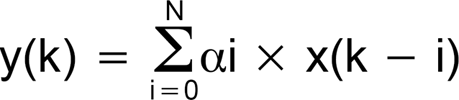
Where k is the time step, y(k) is the filter output at time k, y(k-i) is the sampled input at time k-I, αi is the filter coefficient I, and N is the order of the filter (= number of tape -1).
In addition to the MACS operation the processor handles the task of moving the digital samples and filter coefficients from memory to the MAC hardware, retrieving the results and storing them into memory. In a realtime digital filter algorithm, the computation and memory-move operations have to be completed within one sample period. The number of computations to be performed within one sample period depends on the number of taps of the filter, ie, the order of the filter. The order of the filter is determined by the required filter performance characteristics. When higher order filters are combined with faster sampling rates, the demand on the processor becomes very high. This limits typical MCUs to handle a realtime FIR filter algorithm only at low sample rates and with a reduced number of filter taps.
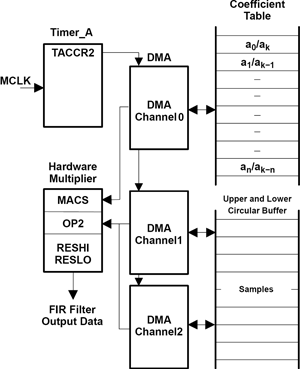
The MSP430F169 with its rich peripheral set handles the FIR filter algorithm in a different manner compared to conventional MCUs. This device has a three channel DMA peripheral that handles the required data, coefficient and result movement between the memory and the MAC, dramatically improving the computation efficiency of the realtime FIR filter algorithm running on-chip.
The DMA peripheral completes a memory transfer operation in two CPU clock cycles. Additionally it has software-selectable trigger sources that make it ideally suitable for the FIR filter implementation. The FIR filter runs on the DMA-MACS-Memory combination autonomously without the intervention of the CPU. The CPU is primarily only being used for the initialisation of peripherals.
The coefficients of the FIR filter are symmetrical in nature. Due to this the coefficient table size can be reduced to half the number of taps of the filter. In a DSP device the input sample data is stored in a circular buffer to implement the movement of the samples through the FIR computation blocks without having to literally move the data in memory. When a new sample is added to the buffer, it automatically replaces the oldest one. A similar circular buffer arrangement is made in the linear memory space of the MSP430 by a folded address structure approach using DMA channels 1 and 2. Figure 1 represents the block diagram of the FIR filter implementation in the MSP430F169.
FIR filter software algorithm
The FIR filter software for the MSP430F169 is written in assembly language to achieve maximum performance. The software is written to accept the coefficients stored in the form of a look-up table pointed to by the label FILTER in program memory. The first value in the look-up table is the value for Timer_A for the required sampling frequency. The next value is the number of filter taps N and the remaining values are filter coefficients.
The depth of the RAM buffer is 2x the number of taps to minimise the circular buffer overhead. In this implementation no additional input or output buffers to the filter structure are provided. These can be added to minimise or eliminate the effect of interrupt latency.
The DMA is configured as follows:
* DMA0: Loads the filter coefficients from the look-up table to the hardware multiplier signed multiply and accumulate (MACS) register.
* DMA1: Sends sample data to MAC and moves the up-direction sample pointer of the circular buffer.
* DMA2: Sends sample data to MAC and moves the down-direction sample pointer of the circular buffer.
The three DMA channels are enabled and disabled together by modulating the TACCR0 register value between 0x00 (disabled) and 0x0B (triggers every 12 clocks).
The computation takes advantage of the symmetrical nature of the FIR filter structure as mentioned in the earlier sections. This algorithm loads the first coefficient value to the MACS register via DMA0 and then moves two samples sequentially to the OP2 register of the hardware multiplier. The first sample is loaded by DMA1 and the second sample by DMA2. DMA1 scans through the upper half of the samples window by incrementing the source address after every transfer and DMA2 scans through the lower half of the samples window by decrementing the source address after every transfer.
Due to the symmetry of the coefficient values only half of the coefficients are stored in the look-up table. If the number of taps, N, is even the first half is stored. If N is odd, then the number of coefficients stored is (N+1)/2 with the last coefficient value divided by two.
The assembly source code for this algorithm is included in the demo code provided as a .zip file along with this application report. The source code can be tailored to specific needs of an application as required.
Demo software
The demo software included with this application report utilises the algorithm described above. The input samples are provided directly to the filter input and to the integrated digital-to-analog converter, DAC0, by a sweep frequency generated using the 12-bit lookup table values from the attached sine wave data file: sine8192_12b.dat. The filter parameters are stored in the program memory pointed by the label 'Filter'. Three examples are shown: a 40-tap low-pass filter, a 224-tap band-pass filter and a 101-tap band-stop filter. The filter output is sent to DAC1 and can be connected to an oscilloscope for viewing of the filter output response. The corresponding input waveform can be seen at the DAC0 output using another channel of the oscilloscope. When the program is downloaded to the device and executed the input frequency sweeps through the set range. The output response can be seen on the channel connected to DAC1 output. The appropriate filter for execution is selected by commenting out the unwanted filter table labels.
The demo software can be run on a FET140 with a MSP430F169 populated in the socket. Note that the FET target board does not have an 8 MHz high frequency crystal or resonator connected to it and must be populated for this demo software to function as is. The software provided with this report is for IAR embedded workbench Kickstart version which can be downloaded for free from the MSP430 Web page.
Calculating the FIR filter coefficients
The filter coefficients and the order of the filter are calculated as per the requirements of the filter type and parameters. This application uses a very inexpensive program called ScopeFIR from www.iowegian.com. Not only does this program calculate the filter coefficients but also simulates the filter responses for all types of FIR filters. The calculated coefficients can be converted to signed fraction hex format by changing the data format and can be imported as text or easily copied and pasted into the assembler source code.
Conclusion
The three channel DMA peripheral with various triggers and the hardware multiplier allows realisation of very efficient FIR filter algorithms using the MSP430F169. Achieving a higher number of taps with faster sampling rate is made possible with this implementation unlike using conventional MCUs that do not have a hardware multiplier to perform MACS and the multichannel DMA to execute the filter algorithm.
Table 1 shows the performance that can be achieved using the MSP430F169 with an 8 MHz CPU clock frequency with respect to filter taps and the maximum sampling rate possible with 100% CPU loading.
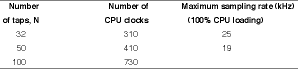
Practical signal processing needs are typically much lower than the maximum possible numbers shown in the table. In such cases more free CPU resources will be available for the user application while running the FIR filter.


© Technews Publishing (Pty) Ltd | All Rights Reserved
 printer friendly version