


Ref: z2816204m
The thermal accelerometers from Memsic are very low cost, dual axis, linear motion sensors with integrated mixed signal conditioning. These linear accelerometers can measure varying and constant accelerations. A special case of constant acceleration is the force of gravity. When the accelerometer is stationary (ie no lateral or vertical accelerations are present) the only force acting on the accelerometer is gravity. The angle between the (vertical) gravitational force, and an accelerometer sensing axis is the inclination angle.
Since the angle lies on a vertical plane defined by the sensing axis and the gravity vector, inclination can be measured from any initial accelerometer orientation. In most designs the accelerometer initial position is either on a horizontal or a vertical PCB (printed circuit board). Each orientation has many tradeoffs which should be considered when choosing the initial position for inclinometry.
Inclination from a horizontal position
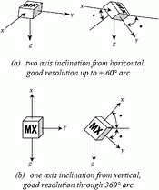
In applications where the inclination angle will not exceed ±60° arc from the horizontal, a single dual axis accelerometer can be used to measure inclination in two axis. Figure 1(a) shows a graphic example of an accelerometer inclination from a horizontal initial position.
To measure inclination a calculation is necessary because the accelerometer output simply represents the acceleration of gravity acting on the sensing axis. The relationship between accelerometer outputs and gravity is given by (reference Figure 1(a)):
Ax = g · sin (α)
Ay = g · sin (β)
Where Ax and Ay represent accelerometer outputs, g is the acceleration due to gravity, and α, β are the inclination angles. To calculate the inclination angle it is necessary to know the inverse of the sine function:
α = sin-1 (Ax/g)
β = sin-1 (Ay/g)
Figure 2 shows the graph of this sine function relation. Note that for inclination angles greater than 60° arc, very little change appears at the accelerometer output. This sine function characteristic is why an accurate measurement of inclination is not possible for angles approaching 90° arc from a horizontal position.
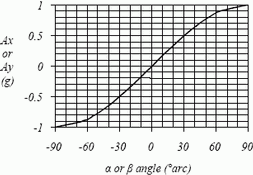
Another interesting observation from Figure 2 is that for small inclination angles the sine function is very close to a linear function:
α = k·Ax
β = k·Ay
In some applications a linear function approximation may meet the accuracy requirements. Table 1 shows the errors in accuracy resulting from using the linear approximation for different inclination ranges. To calculate k for each inclination range a linear curve fit was performed.
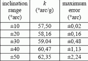
With the linear function approximation the accelerometer sensitivity is converted into an inclination sensitivity by dividing by k. For example, if the accelerometer sensitivity is 1000 mV/g and the inclination range is ±20° arc, the inclination sensitivity would be:
(1000 mV/g) / (58,16° arc/g) = 17,2 mV/°arc
Note that the voltage output change for a small inclination angle is relatively small (17,2 mV for 1° arc), so careful consideration to noise must be applied in inclinometer designs. A Memsic ultra low noise accelerometer with a noise filter that limits the bandwidth to 1 Hz will display a noise level in the order of 1 mVr.m.s. With such an accelerometer the inclination output noise would be less than 0,1° arc r.m.s. In summary, the linear function approximation simplifies the acceleration to inclination calculation, with a small measurement error penalty.
Inclination from a vertical position
When inclination measurement is needed for angles >90° arc, the x and y accelerometer outputs can be combined to obtain good resolution for angles through a 360° arc range. With this approach, one dual axis accelerometer is needed to measure a single axis of inclination. Figure 1(b) shows a graphic example of an accelerometer inclination from an initial vertical position.
The relationship between acceleration and inclination angles in this configuration is (reference Figure 1(b)):
Ax = g · sin (δ)
Ay = g · sin (γ)
In this configuration (δ + γ) = 90° arc, so it suffices to know either one of δ or γ. The Ax relationship above can be rewritten as:
Ax = g · sin (-γ + 90° arc) = g · cos (γ)
Dividing the two equations above gives:
[Ay/Ax] = [(g · sin (γ))/(g · cos (γ))] = tan (γ)
So the inclination angle γ can be calculated by applying the inverse of the tangent function:
γ = tan-1 [Ay/Ax]
In addition to providing good inclination resolution at any angle, the vertical mounting offers another advantage. Errors that are common to both outputs are removed in the signal process of dividing Ay by Ax. For example, temperature compensation of accelerometer sensitivity is not necessary when applying this inclination measurement approach.
Since thermal accelerometers display predictable and repeatable variation of sensitivity due to temperature, both outputs display the same scale change, and the result of the ratio calculation is not affected by sensitivity changes due to temperature.
A convenient method to implement the signal processing necessary for this measurement approach is to use a microcontroller (see Figure 3).

Many 8-bit microcontrollers are suitable for the task, but they do not include the tan-1 function in their math library due to their size constraints. The microcontroller programmer then has to implement the tan-1 function using a lookup table or a math approximation (ie Taylor series, 2nd or 3rd order polynomial, etc).
Given that the accelerometer outputs Ax and Ay have been acquired (through an A/D converter or with a timer if using the digital output accelerometer), the polarity of the Ax and Ay outputs determines the inclination angle quadrant in the tan-1 calculation. The program listing in Figure 4 shows an example of the quadrant correction assuming that the function arctan() returns an angle in the range -π/2 to +π/2.
<z2816204me.png**>
Inclinometer implementations
Many considerations have to be made when choosing the signal processing method necessary to convert the accelerometer output to an inclination measurement. Each design will have its own set of variables, ie analog or digital control system interface, inclination range, mechanical mounting constraints, temperature range, etc. Many of the signal processing steps that are used to meet the application requirement are shown in Figure 5, though not all these steps are necessary for every application.
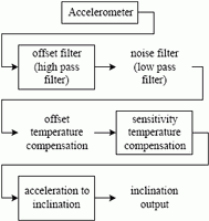
In an application operating in a relatively constant temperature environment, where small inclination angles are to be measured, the only processing necessary may be the noise filter.
In applications where a change of inclination is of concern (the actual inclination angle is not necessary), like in automobile and motorcycle security alarms, a high pass filter can be used to eliminate the need for temperature compensation of offset. The high pass filter displays changes of inclination that occur relatively fast, but it will not display changes in offset that occur slowly, such as the variations due to temperature.
In precision or high accuracy applications, where angles >90° arc need to be sensed, the noise filter and the offset temperature compensation may be necessary.
| Tel: | +27 11 608 0144 |
| Email: | [email protected] |
| www: | www.nuvisionelec.com |
| Articles: | More information and articles about NuVision Electronics |


© Technews Publishing (Pty) Ltd | All Rights Reserved
 printer friendly version