
Ref: z2816205m
Due to their function, mobile stations are mostly arrayed in exposed locations. The third generation (3G) of mobile communication, such as UMTS or CDMA, is also therefore still at risk of being struck by lightning. This article describes the selection and installation of surge voltage protection devices, while also taking into consideration the requirements of the mobile communications market.
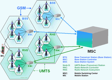
Image loss
By implementing a surge voltage protection concept, mobile communication operators lay an important foundation for the continuous operating safety of the entire infrastructure (Figure 1). Losses in turnover of 500 Euros per second are likely in the case of MSC location blackouts. This underlines the necessity for detailed planning. It can take several hours until the faults have been found and eliminated, during which time the user has to simply accept the system blackout. Due to the ever-increasing competitiveness in the mobile communications sector, system availability is becoming a crucial survival factor.
Arrester requirements
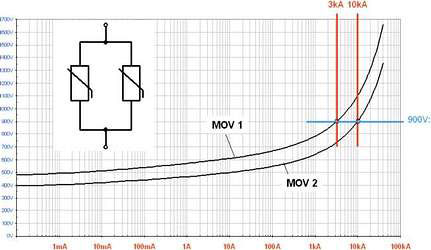
The use of lightning current and surge voltage arresters is standard in mobile communication stations. However, for the use of lightning current arresters (class I) in three-phase power supply systems, IEC 60354-5-53 demands a lightning test current (Iimp) of at least 12,5 kA (10/350 μs) per channel. MOVs (metal-oxide varistors), having a lightning current capacity of approximately 3 kA (10/350 μs) and generally used as class II conductors, do not meet these requirements. You would need to connect at least five of these devices in parallel. However, the tolerances of varistors do not permit such a simple summation of the surge currents, as unsymmetric strain occurs - comparable to paralleling fuses - and the desired effect does not show (see Figure 2).
The requirements of the entire arrester combination regarding the lightning current capacity, are derived directly from the protection level determination according to IEC 61024-1.
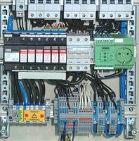
If no risk analysis has been performed, it is assumed that 50% of the lightning current is distributed to the power lines connected to the system. DIN VDE 0855 part 300 stipulates lightning protection measures of 100 kA for protection level III in transmission and reception systems. Therefore, the inner lightning protection requirement amounts to at least 50 kA (10/350 μs) for the entire arrester combination. The required space, as well as the price of combinations for 50 kA, as compared to 100 kA, is really minimal, ensuring that the more powerful variant is generally put to use. This is why Phoenix Contact's Powerset BC... is designed up to protection level I with 200 kA rating (Figure 3). Fitted with integrated potential-free remote contact, the trouble-free status of the arrester combination is transmitted along with the optical status display. Combined with a maximum width of 140 mm, the Powerset BC... has became an international standard.
Co-ordination of arresters
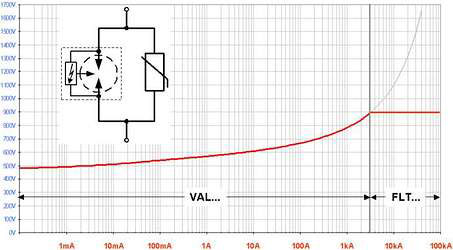
Combinations of Class I arrester Flashtrab and Class II arrester Valvetrab connected in parallel according to the active energy control (AEC) principle represents the current state of technology. A self-contained, powerful MOV-based Valvetrab initially takes over the conducting process due to its quick reaction time and simultaneously generates the protection level for the connected system. In contrast to the classic co-ordination concept with inductive decoupling, the pluggable, MOV-based class II arresters' voltage drop is monitored here, instead of the current gradient. Having knowledge of its characteristic curve, this voltage provides unambiguous information about the current performance. Before the maximum allowable energy strain is exceeded, the Flashtrab actively triggered, thus preventing an overload of the MOV (Figure 4). Valvetrabs are integrated into every conducting process and therefore pluggable to enable exchange, without the necessity of switching off the affected locations.
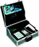
A test device, the Checkmaster for the pluggable arresters, monitors and logs the current status of these modules during the revision work and shows possible ageing early on (see Figure 5). This reduces maintenance work to the intervals stipulated by the mobile communication operator.
Fluctuation in power supply systems
Heavily fluctuating low-voltage power supplies, which sometimes have voltages exceeding the arrester rated voltage UC, represent an impermissible strain. Especially in the mobile communications sector, where long power supply feeds have to be considered, it happens again and again that surge protection devices (SPD) are destroyed in spite of a correct choice of lightning current carrying capacity. The reason for this is often a short circuit in the power supply, which could not be interrupted in due time by fusing elements, possibly due to long feeds or an insufficient cross-section (within 5 seconds). During this period, there are therefore two arrester paths with impermissible voltages in a three-phase system. An interruption of the neutral conductor can have the same result. Often it is only the MOV-based arrester (class II) that is visibly destroyed by this.
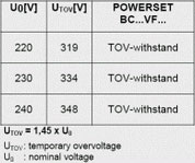
These devices are designed for surge voltages in the μs range; not for stationary overvoltages occurring over an extended period of time. The thermal disconnection required according to IEC 61643-1 is merely designed to cope with the on-going ageing process and is therefore not able to cut off the arrester from the power supply in due time. A fire risk cannot be excluded. In IEC 61643-1, a TOV-withstand test (TOV: temporary overvoltages) is also described, according to which SPD can be operated at an increased voltage for 5 seconds:
UTOV = 1,45 x U0 = 1,45 x 230 V
UTOV = 3345 V
The SPDs have to pass this test with the criteria TOV-failure (test passed, SPD inapplicable) or TOV-withstand (test passed, SPD in function).
Installation guideline IEC 60364-5-53 recommends the use of SPDs that pass this test with a TOV-withstand result. According to the test, only arresters with UC > UTOV are fully functional as well as suitable for use at increased voltage over an extended period of time. An arrester rated voltage of UC > 350 V is recommended for standardised use worldwide, eg Powerset BC...VF... (See Table 1).
What about the antennas?
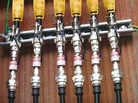
Also at risk from atmospheric discharges are the antenna cables, which cross buildings and are often very long, and the antennas themselves. Cables with a coaxial structure are used for this reason. These generally have suitable EMC characteristics and can be connected to the ground potential in defined intervals. However, there is always a certain risk of a transient interference in these systems and their spread to sensitive interfaces. The safety of the entire facility can only be increased through the connection of SPDs like Coaxtrab to the antenna system (Figure 6).
The safety requirements for telecommunication lines according to IEC 61643-22 is not discussed here in any more detail.
Conclusion
The high arrester rated voltages UC of the AEC combinations, as well as their possible application in facilities rated according to lightning protection classes I, II, III and IV, considerably simplify their selection for global use. The verifiability of the pluggable variants rounds off the optimisation nicely, also with regard to the maintenance costs.
| Tel: | +27 11 801 8200 |
| Email: | [email protected] |
| www: | www.phoenixcontact.co.za |
| Articles: | More information and articles about Phoenix Contact |

© Technews Publishing (Pty) Ltd | All Rights Reserved