How they work: RFID transponders
22 February 2006
Telecoms, Datacoms, Wireless, IoT
Radio frequency identification (RFID) is the system of using radio signals to send information identifying a particular situation or item. It can be used to track and locate any item including material, people and animals.
There are two major components in a radio frequency identification (RFID) system:
1. The tag (transponder) programmed with unique information.
2. The reader (interrogator) includes a decoder to interpret data.
The tag consists of an integrated circuit (IC) and a coupling device. The IC stores specific data unique to that tag. The coupling devices interfaces with the reader.
The RFID transponder coil is part of the coupling device and acts as the transmitting antenna. The key specifications of the transponder coil are sensitivity and read distance. However, the inductance (L) of the transponder coil directly influences the sensitivity and the read distance. Generally, a higher inductance provides greater sensitivity resulting in a longer read distance. The manufacturer of the tag usually specifies the inductance of the coil to be used. The read distance is defined as: the maximum distance from the reader that the transponder responds to the reader's magnetic field.
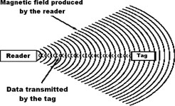
When the reader receives the transmitted data, it interprets the data and takes appropriate action. When the transponder enters the field produced by the reader, the coil produces a voltage inside the tag. In a passive transponder, this voltage can be used to power the tag. In an active transponder, the voltage is used to wake the tag and use its internal battery.
Figure 1. The reader produces a magnetic field that triggers the tag
Active transponders generally have longer read distances, shorter operational life and are larger and more costly to manufacture. Passive transponders are generally smaller, have a longer life and are less expensive to manufacture.
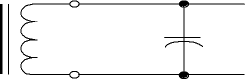
For optimum performance, the transponder coil is used in a parallel LC circuit as shown in Figure 2. Adding a capacitor to the circuit maximises the read distance. The LC circuit is designed to resonate at the operating frequency of the reader.
Figure 2. The LC circuit is designed to resonate at the operating frequency of the reader
The following equation is used to calculate the value of the capacitor:
C = 1/[L * (2 Π * frequency)²
For example: to calculate the capacitor value for a 4,9 mH transponder coil operating at 125 kHz:
C = 1/[0,0048 * (2 Π * 125000)²
= 3,308E-10
= 331 pF
Fastron's transponder coils are wirewound, surface mount antennas, designed for use in 125 kHz RFID systems. They are rated for 125 μC operation.
Further reading:
Smart farming with LoRaWAN
Otto Wireless Solutions
Telecoms, Datacoms, Wireless, IoT
Real-time visibility is transforming modern agriculture, and Otto Wireless Solutions, together with Dragino, deliver this capability through a comprehensive suite of long-range IoT sensors and gateways designed for smart farming.
Read more...
RTK-enhanced GNSS and INS solution
Dizzy Enterprises
Telecoms, Datacoms, Wireless, IoT
This latest XSENS MTi-8 Click provides high-accuracy positioning (RTK-supported) and orientation tracking in demanding outdoor embedded applications.
Read more...
High-performance double balanced RF mixer
RFiber Solutions
Telecoms, Datacoms, Wireless, IoT
The AM5008 from Mercury Systems is a high-performance, double-balanced MMIC mixer designed for wideband applications spanning 2 GHz to 24 GHz.
Read more...
Compact NFC antennas enable easy integration
Telecoms, Datacoms, Wireless, IoT
Leankon has expanded its 13,56 MHz NFC antenna portfolio with a comprehensive suite of nine off the shelf products designed for next generation IoT applications.
Read more...
Ultra-low jitter clocks
Altron Arrow
Telecoms, Datacoms, Wireless, IoT
Skyworks has introduced a new family of ultra-low jitter programmable clocks designed to meet the increasing demands of next-gen connectivity.
Read more...
Efficient Bluetooth SoC
Altron Arrow
Telecoms, Datacoms, Wireless, IoT
The EFR32BG29 wireless SoC from Silicon Labs is a highly efficient, high memory, low-power, and ultra compact SoC designed for secure and high-performance wireless networking for IoT devices.
Read more...
Minimal size, maximum flexibility
Würth Elektronik eiSos
Telecoms, Datacoms, Wireless, IoT
Würth Elektronik has introduced two highly compact radio modules that give developers maximum freedom in designing proprietary wireless solutions that go beyond standard protocols.
Read more...
Super Wi-Fi extends industrial connectivity
NEC XON
Telecoms, Datacoms, Wireless, IoT
Africa’s harshest mines, ports, and industrial parks are no longer bound by range, latency, and interference challenges.
Read more...
HackRF Pro advances Open SDR performance
IOT Electronics
Telecoms, Datacoms, Wireless, IoT
Designed for engineers, researchers, and radio enthusiasts alike, the HackRF Pro can transmit and receive signals across a wide frequency range of 100 kHz to 6 GHz, making it a versatile tool for testing and developing modern and emerging radio technologies.
Read more...
Deterministic high-speed Ethernet
Telecoms, Datacoms, Wireless, IoT
The Fraunhofer Institute for Photonic Microsystems IPMS has developed a new 10G TSN endpoint IP Core, enabling deterministic real-time communication at data rates of up to 10 Gbit/s.
Read more...


 printer friendly version