


Many developers, whether they are measurement and control technicians or electronic technicians, are confronted with the phenomenon of 'power supplies'. A re-occurring phenomenon is the supply of suitable voltages at the correct location.
Despite careful selection of power supplies to parameters such as voltage, current, performance, static and dynamic stabilisation and also the ripple effect, to name but a few requirements, the power supply does not function as expected.

Instead of the required 5 V only 4,3 V is measured on the user's board - the switching, which has been arranged for 5 V, will more or less work. Hopefully less, then this mistake will be noticed at the test stage and not later when the customers start to use it. But what are the reasons for these phenomena?
Contacts, transfer resistances and other unknown factors
Unwanted voltage loss develops in contacts and cables, but also on connection clamps and connectors. For the experienced developer the easiest to calculate is the cabling. It is well known that the specific resistance of copper is 0,0175 (Ω x mm²)/m at 20°C. Therefore, in the case, for example, of 10 A current through a cable of 1 mm² diameter, 0,175 V is lost. If the voltage loss is too large, there is a sure way to cure this: increase the diameter. A diameter that has doubled in size has half as much voltage loss. This can be calculated very easily. But what happens to the transfer losses on the contacts to the power supply and the user's board? This cannot be calculated as easily.
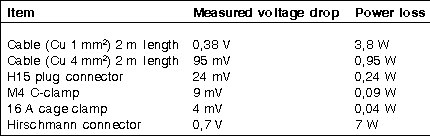
Table 1 shows examples of voltage losses of various cables and connectors, each time measured at 10 A current load. It becomes clear how quickly the losses can reach the voltage area. Often the user has to live with long cables and few cross sections, as large cross sections complicate the cabling. How can he avoid unwanted voltage losses despite all of this?
Local/remote sensing
The answer lies with more, or less, efficient power supplies. More efficient is a power supply, which is equipped with so-called remote sensor connections. Here the regulator can 'feel' the output voltages. Through the separately-wired sensor cables, the regulator sees the voltage conditions at the right location. It asks for more output voltage, in order to achieve the exact required load of 5 V and to keep it stable. Existing transfer resistances of the contact and cables are thereby compensated for. Even thermal changes of the transfers are securely balanced. But here two mistakes can be made.
It can happen, that despite correct cabling with sensor cabling to the load point, the whole system collapses at a certain load, ie, totally fails or even starts a new cycle. What has gone wrong?
One possibility: the voltages losses are compensated, however, the voltage loss from a certain current is too much. After multiplying one of the bad values in Table 1 (0,4-38 V per cable) and the current load at max 10 A, this possibly creates an unwanted strain on the power supply. In this example the power supply would have to make available 2 x 0,38 V x 10 A + 7,6 W. If a 50 W power supply is operating at total capacity, this could mean that the 7,6 W could shut the complete system down.
The static behaviour has been explained. But what problems can occur when the dynamic load changes?
This technology of remote sensing in respect of the sensor cables has one disadvantage. It influenced the reaction time of regulator within the power supply. As every electronics expert has learned in basic studies, cables represent an inductance. This relates to the power cable, as this can create unwanted dynamic effects through changes in the current load, with which the regulator has to battle. It becomes clear very quickly, how well, ie, with how many phases and dynamic reserves, the regulator has been equipped. With the sensor cable operation (red graph: Figure 2) it can be seen that the regulating cycle is still stable, however, the reaction time, the voltage jumpers and breakers are considerably larger than in the yellow graph shown in Figure 2.
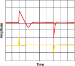
Here the regulator does not have to battle with the cable inductance, therefore the reaction times and voltage deviations are only half as large. A further disadvantage has to be mentioned: the immunity and the interferences of the power supply can be influenced by the sensor cables. This concerns electromagnetic radiation, as well as coupled interferences such as burst. The important measure here is to 'drill in' the sensor cables or shield them. Power supplies from Schroff are therefore equipped with 'drilled in' sensor cables of 1 m length. The protection against interference is achieved with filters and protective measures suited to the power supplies.
When cabling has to be long
However, there are applications where extremely long cables are required but no sensor cables are permitted. Of course, the output voltage still has to be correct.
This can be secured by increasing the load by exactly the amount that is measured for the voltage loss of the power cables. This, however, is a manual matter and has to be repeated when a network component has been exchanged. A certain amount of failure can be expected, especially, when several power supplies within a system have to supply different voltages. In just such cases the power supplies have to be balanced individually and cannot be exchanged with neighbouring units.
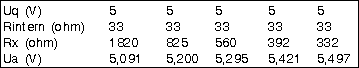
Schroff has solved this problem recently in connection with a customer project. The output voltage of the individual standard power supplies (Vq = 5 V) in the customer systems are regulated via programming resistors that are installed on the connectors. These programming resistors (Rx) cause a definite change of the output voltage. In connection with internal resistors a voltage separator is created that can be influenced via Rx, so that the size of Rx determines the resulting output voltage VA of the power supply (Table 2). Thus standard units can be exchanged amongst each other. Also in the case of a service exchange, the corresponding slot will retain the required output voltage.
The correct voltage in the right location can be achieved. With knowledge and skill, the worst mistakes can be avoided.
| Tel: | +27 11 608 3001 |
| Email: | [email protected] |
| www: | www.actum.co.za |
| Articles: | More information and articles about Actum |


© Technews Publishing (Pty) Ltd | All Rights Reserved
 printer friendly version