


The switching power supply has replaced the linear power supply gradually. It is widely used in all kinds of electronic equipment, including module type sources, driver type sources, UPS and battery chargers. Applications of switching power supplies can be found in many industrial and commercial areas.
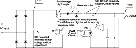
Switching power supplies are a large improvement on the high volume, heavy weight and low efficiency of linear power supplies. The principle of operation of the switching power supply is shown in Figure 1. It connects directly from the AC power (off-line) without going through the low-frequency transformer. Because of the high input AC voltage, the buck capacitor can be smaller. Switching power supplies use high-frequency transistors to chop the high DC voltage (rectified from AC source) into a high AC voltage and then convert it into the rated voltage through the high frequency transformer. It is then rectified into the rated DC voltage. Due to the high frequency switching, there are ripple noises generated from the switching transients, which need to be taken care of.
Switching power supply circuit theory
Among all the DC-to-DC converters, SMPS (switch mode power supplies) can be divided into three basic circuit structures based on input voltage, output voltage and polarity:
* Step-down or buck converter: used for output voltage lower than input voltage.
* Step-up or boost converter: used for output voltage higher than input voltage.
* Inverter or buck-boost converter: the third one is used when the output polarity is inverted from the input. This kind of circuit can also be used in both step-up and step-down conditions.
If we need to isolate the input and output, the above three basic circuits cannot be used any more. Instead we must convert these three types to Forward type, Flyback type, Half-bridge type, Push-pull type, or Full-bridge type circuit structures. There are two ways to generate the switching signal: one is the self-oscillation circuit where its frequency is decided by output load and input voltage; the other is the pulse-width modulator (PWM) IC where its frequency is decided by the control IC.
Non-isolated types
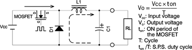
* Buck regulator: when the switch is ON, power is transferred to the load through L1 and also stored in L1 at the same time. When the switch is OFF, power will be supplied by L1 and transferred to the load through D1 and L1.
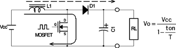
* Boost regulator: when the switch is ON, power is stored in L1. When the switch is OFF, power will be transferred to the output load through L1 and D1. Output voltage can be higher than the input because of the pre-stored voltage at L1.
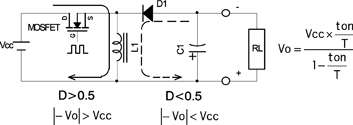
* Buck-boost regulator: when the switch is ON, the power is stored in L1. When the switch is OFF, the power is transferred to the output load through L1 and D1.
Isolated types
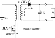
* Flyback converter: when the mosfet (switch) is ON, the power is stored in the transformer, and when the mosfet is OFF, the power is transferred to output load from the transformer.
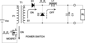
* Forward converter: when the mosfet (switch) is ON, the power is transferred to the output and stored in L1 through D1 and the transformer. When the switch is OFF, the power stored in L1 will be transferred to the load through D2.
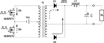
* Push-pull converter: when switch 1 is ON (switch 2 is OFF), power is transferred to the output load through the transformer and D1. When switch 2 is ON (switch 1 is OFF), power is transferred to the output load through the transformer and D1.
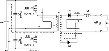
* Half-bridge converter: when switch 1 is ON (switch 2 is OFF), power is transferred to the output load through the transformer, C2, and D1. When switch 2 is ON (switch 1 is OFF), power is transferred to the load through the transformer, C1, and D2.
* Full-bridge converter: when switches 1 and 4 are ON, switch 2,3 are OFF), power is transferred to the output load through the transformer and D2. When switches 2 and 3 are ON (switches 1 and 4 are OFF), power is transferred to the load through the transformer and D1.

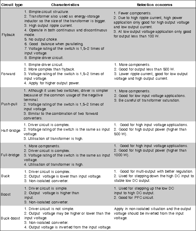
The characteristics of each type are shown in Table 1. For assistance and advice about your power supply requirements, contact your local MeanWell representative.
| Tel: | +27 11 462 4253 |
| Email: | [email protected] |
| www: | www.rectifier.co.za |
| Articles: | More information and articles about Current Automation |


© Technews Publishing (Pty) Ltd | All Rights Reserved
 printer friendly version