


Counter and timer modules are often incorporated in CPLD (complex programmable logic device) designs. But, while counters and timers are ideal for some designs, they are not so ideal for designs that need greater resolution.
This article demonstrates how to double timer/counter resolution by using DualEDGE-triggered registers in CoolRunner-II CPLDs, and includes a design trick to achieve higher frequency beyond the device's maximum specified frequency, FMAX.
Timer/counter units are found in many applications. In some cases, they are used to measure elapsed time by counting processor cycles or clock ticks. For example, to generate a pulse width modulation (PWM) signal by using two different initial or terminal count values, and a one-shot timer that toggles the I/O pin on overflow, the pin could be set to 1 for a desired amount of time, then 0 for a different amount of time, then 1 again, and so on. The period of the PWM signal in this case is a function of the sum of the two timer periods, and the duty cycle is the length of time that the pin is set to 1 as a percentage of the period.
PPWM = Ptimer1 + Ptimer2
DutyCycle = 100 x t1/(t0 + t1)
PWM waveform accuracy is dependent on the input clock frequency. A 100 MHz clock can generate resolution accuracy of 10 ns. For a PWM waveform with 100 ns period and 60% duty cycle, the terminal count for '1' is six and for '0' is four for a 100 MHz counter. For the same period with 55% duty cycle (55 ns) at 100 MHz, the counter will have a problem since it cannot count to 5,5. It will require a 200 MHz clock, which has 5 ns resolution, and count to 11 for 55 ns.
The CoolRunner-II CPLD with DualEDGE triggered registers is the ideal solution for this type of application. It can achieve 200 MHz counter resolution while using a 100 MHz clock, and solve the resolution problem while also maintaining the low power and low noise operation.
DualEDGE registers
CoolRunner-II DualEDGE triggered registers allow designers to reach unprecedented performance levels. These CPLDs can double system performance by creating DualEDGE Triggered (DET) registers. CoolRunner-II DET registers allow data to be registered on both the rising and falling edge of a clock. DET registers can be used for logic functions that include shift registers, counters, comparators, and state machines. Designers must evaluate the desired performance of the CPLD logic to determine use of DET registers. The DET register is available on all macrocells in all devices of the CoolRunner-II family.
Doubling resolution using DualEDGE
DualEDGE registers allow CoolRunner-II CPLDs to effectively double the resolution of any clocked operation. Let us examine a system that needs 5 ns of resolution. Given a 100 MHz clock in a conventional system, this would be impossible, as 10 ns is the best achievable resolution. However, if a counter is implemented with DualEDGE, it can actually accept a 100 MHz external clock, and count at an internal frequency of 200 MHz, giving us the needed 5 ns of accuracy.
Putting DualEDGE to use
Let us use a more realistic example, rather than using perfect, round integer values. Imagine a system that requires a 2,35 MHz (425 ns period) clock output from the CoolRunner-II device, given a 100 MHz (10 ns) clock input. There is insufficient resolution given a 100 MHz input, and hence we need to use DualEDGE registers to complete the task. A 100 MHz clocked Dual Edge register would provide the equivalent of a 5 ns period. So, the DualEDGE counter would need to count 85 clock cycles in order to create a 425 ns period output clock (see Figures 1 and 2).
It should be noted that although the DET registers can double the system performance with a lower frequency clock input, the DET registers cannot exceed the device maximum operating frequency (FMAX). For example, the FMAX for XC2C64A is 263 MHz, so the incoming clock FMAX for the DET register must be 131,5 MHz or less.
Beyond FMAX with a simple design trick
Let us say we need to generate a 2,34 MHz clock from a 200 MHz internal clock. Using the same trick as above, a 2,34 MHz frequency corresponds to a 427,5 ns clock period, and a 200 MHz frequency corresponds to a 5 ns clock period. In theory, using 200 MHz DualEDGE registers would allow a terminal counter to be clocked at an internal frequency of 400 MHz (2,5 ns resolution). Given this 2,5 ns resolution, we would simply need to count to a terminal value of 171 in order to generate a 2,34 MHz clock (427,5 ns period). But alas, as stated above, DualEDGE Triggered registers can only be clocked at an external frequency of FMAX divided by two, or less: fEXT ≤ fMAX/2.
Hence, we need another solution
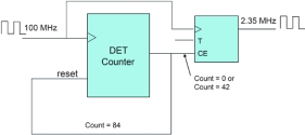
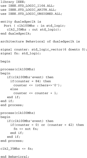
In order to generate a 2,34 MHz (427,5 ns period) clock from an input frequency of 200 MHz (5 ns resolution), we would need to have a terminal counter count to a value of 85,5. Notice that there is not enough resolution! Here is a trick. We internally invert the incoming clock to the counter immediately after the counter counts to an integer value of 84. Doing this ensures that the next count will occur on the falling edge of the 85th clock cycle. This gives us the ´ cycle worth of resolution needed to count to 85,5. Figure 3 shows a block diagram of this circuit.
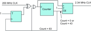
From Figure 3, the counter counts to 84 (0 to 83) and toggles the left T register. This inverts the 200 MHz clock such that the counter actually counts on the next falling edge of the 200 MHz clock. The OR gate before the counter ensures that there is no glitch during the clock inversion process.
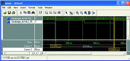
Figure 4 is a simulation waveform for this design. It shows that the CoolRunner-II device is capable of generating a 2,34 MHz clock from a 200 MHz input signal.
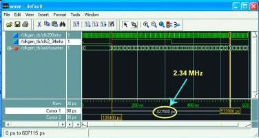
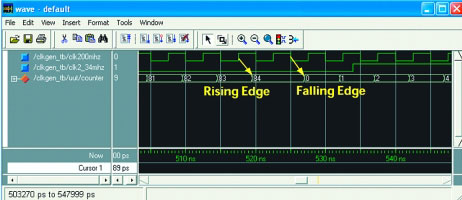
Figure 5 shows how, after the 84th rising edge, the clock is internally inverted, and the counter proceeds to count on the falling edges. Note the Tco delay as this is a timing simulation.
Conclusion
CoolRunner II CPLDs are the ideal solution for providing the highest resolution for Timer/Counter applications. CoolRunner-II CPLDs are targeted for applications that require both low power consumptions and high performance.


© Technews Publishing (Pty) Ltd | All Rights Reserved
 printer friendly version